
Coating pressure barrel capable of accurately controlling temperature

A technology of precise temperature control and pressure barrel, which is applied in the direction of pressure vessels, coatings, and devices for coating liquid on the surface, etc., can solve problems such as temperature changes of coatings, achieve the effects of reducing influence, facilitating production, and reducing the rate of defective products

Pending Publication Date: 2021-11-02
上海允孚新材料科技有限公司
View PDF0 Cites 0 Cited by
  • Summary
  • Abstract
  • Description
  • Claims
  • Application Information

AI Technical Summary

Problems solved by technology

[0007] In order to solve the above technical problems and enable the paint temperature to be automatically adjusted according to requirements during the production process, the present invention provides a paint pressure barrel capable of precise temperature control, which is used to solve the problem of paint temperature changes

Method used


Image

  • Coating pressure barrel capable of accurately controlling temperature
  • Coating pressure barrel capable of accurately controlling temperature
  • Coating pressure barrel capable of accurately controlling temperature

Examples


Embodiment 1

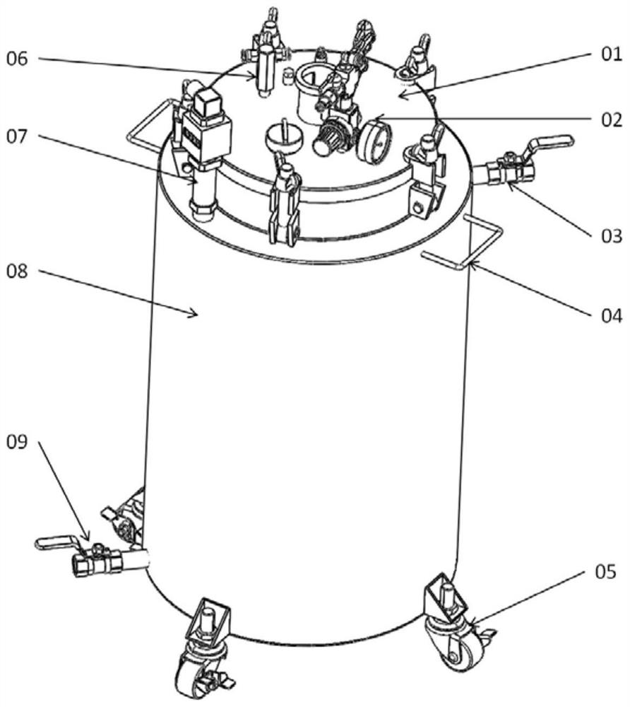
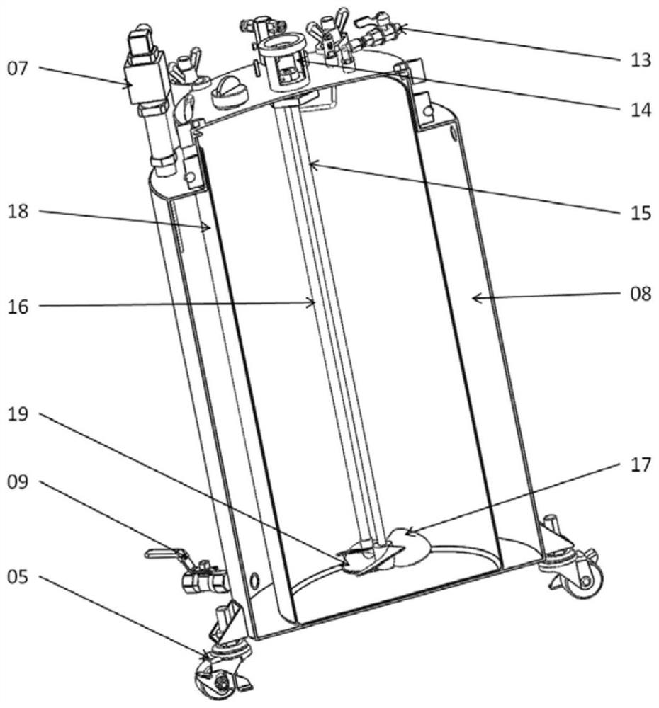
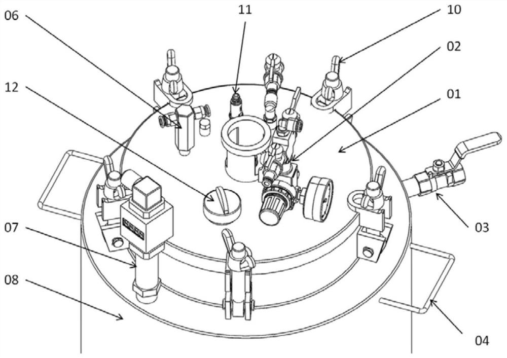
[0030] Embodiment one, such as Figure 1 to Figure 4 As shown, a paint pressure barrel that can precisely control the temperature, on the basis of the existing paint pressure barrel, divides the barrel body into an outer barrel 8 and an inner barrel 18, and the cavity between the outer barrel 8 and the inner barrel 18 is connected to the inlet The ball valve 09 and the outlet ball valve 03, and the inlet ball valve 09 is arranged on the bottom side of the outer tub 8, the outlet ball valve 03 is arranged on the top side of the outer tub 8, and the cavity part of the inner tub 18 and the outer tub 08 is filled with an external cold water or hot water circulation device, so as to This is used to adjust the temperature of the paint in the inner barrel 18. An integrated digital display temperature sensor 07 is added to the shoulder of the outer barrel 08, which can not only monitor the water temperature and display the temperature value in real time, but also transmit the temperatu...

Embodiment 2

[0032] Embodiment two, such as Figure 5 to Figure 7 As shown, a paint pressure barrel that can precisely control temperature, the pressure barrel adopts a single-layer structure, a circular spiral coil 25 is added inside the barrel body 23, and the external cold water is connected through the spiral coil inlet ball valve 24 and the three-way outlet ball valve 22 Or a hot water circulation device, the paint is directly filled in the barrel, and the circulating water flow in the circular spiral coil 25 is utilized to regulate the temperature of the paint. A small integrated digital display temperature sensor 21 is added to the three-way outlet ball valve 22 to monitor the water flow temperature in real time and display the temperature value, and at the same time transmit the temperature signal to the external temperature control device, so as to realize automatic monitoring and real-time accurate automatic adjustment of the water temperature. The paint temperature is kept withi...


PUM


Abstract

The invention relates to a coating pressure barrel capable of accurately controlling the temperature. The coating pressure barrel comprises a barrel body, a temperature adjusting device is arranged in the barrel body, the temperature adjusting device is connected with an external temperature control device, and the external temperature control device is connected with an integrated digital-display temperature sensor for measuring the temperature in the barrel body. The real-time temperature of a coating can be accurately measured, the technological process is better met, production by spraying workers is facilitated, and the rate of defective products is reduced; and after a coil pipe is additionally arranged, the coating in the barrel can be heated or cooled through an external water circulating device, so that the temperature of the coating is kept in a technological requirement range, and the influence of the environment temperature on the temperature of the coating in the pressure barrel is reduced.

Description

technical field [0001] The invention belongs to a painting pressure barrel, in particular to a paint pressure barrel capable of precise temperature control. Background technique [0002] The technical solution adopted by the prior art for paint pressure barrels is: the existing pressure tank is an inner and outer double-layer barrel, the inner barrel is filled with paint, the outer barrel is tightly fastened with the barrel lid, and the external air pipe is used to fill the compressed air to maintain the required air pressure in the barrel. Spray pressure. A stirring motor is installed on the barrel cover to stir the paint during work to prevent the paint from agglomerating or depositing. [0003] The disadvantages of the prior art are: [0004] (1) It is impossible to accurately measure the paint temperature in the pressure tank. The paint pressure tank needs to monitor the paint temperature in real time according to the process requirements in some operating environments...

Claims


Application Information

Patent Timeline
Patent Type & Authority Applications(China)
IPC IPC(8): F16J12/00B05C11/10B05C11/11F25D17/02F25D29/00F25D31/00
Inventor 张来玉郭源
Owner 上海允孚新材料科技有限公司
Learn More