
Welding flux drying machine

A dryer and flux technology, applied in dryers, drying, drying of solid materials, etc.

Active Publication Date: 2021-11-02
泰和县鹏翔挂车制造有限公司
View PDF5 Cites 0 Cited by
  • Summary
  • Abstract
  • Description
  • Claims
  • Application Information

AI Technical Summary

Problems solved by technology

[0005] In order to solve the problems of flux drying and particle size screening, the present invention proposes a flux dryer

Method used


Image

  • Welding flux drying machine
  • Welding flux drying machine

Examples


Embodiment Construction

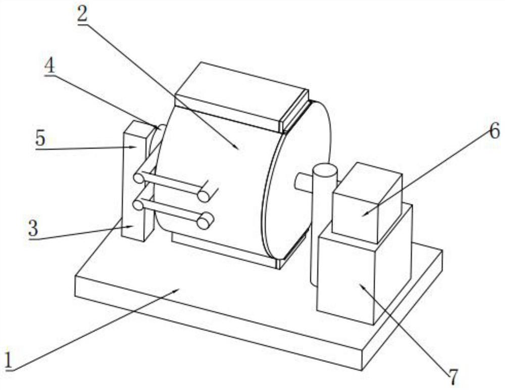
[0018] A flux dryer, comprising a base 1 and a working chamber 2, wherein: a support base 3 is fixed on the left side of the base 1, a heat blower 4 is connected to the support base 3, and a There is an exhaust fan 5, a motor 6 is fixed on the right side of the base 1, a control compartment 7 is arranged below the motor 6, a working compartment 2 is installed between the motor 6 and the hot blower 4, and the motor 6 can be Drive the working chamber 2 to rotate, and the hot air blower 4 is fixed on the left side of the working chamber 2.

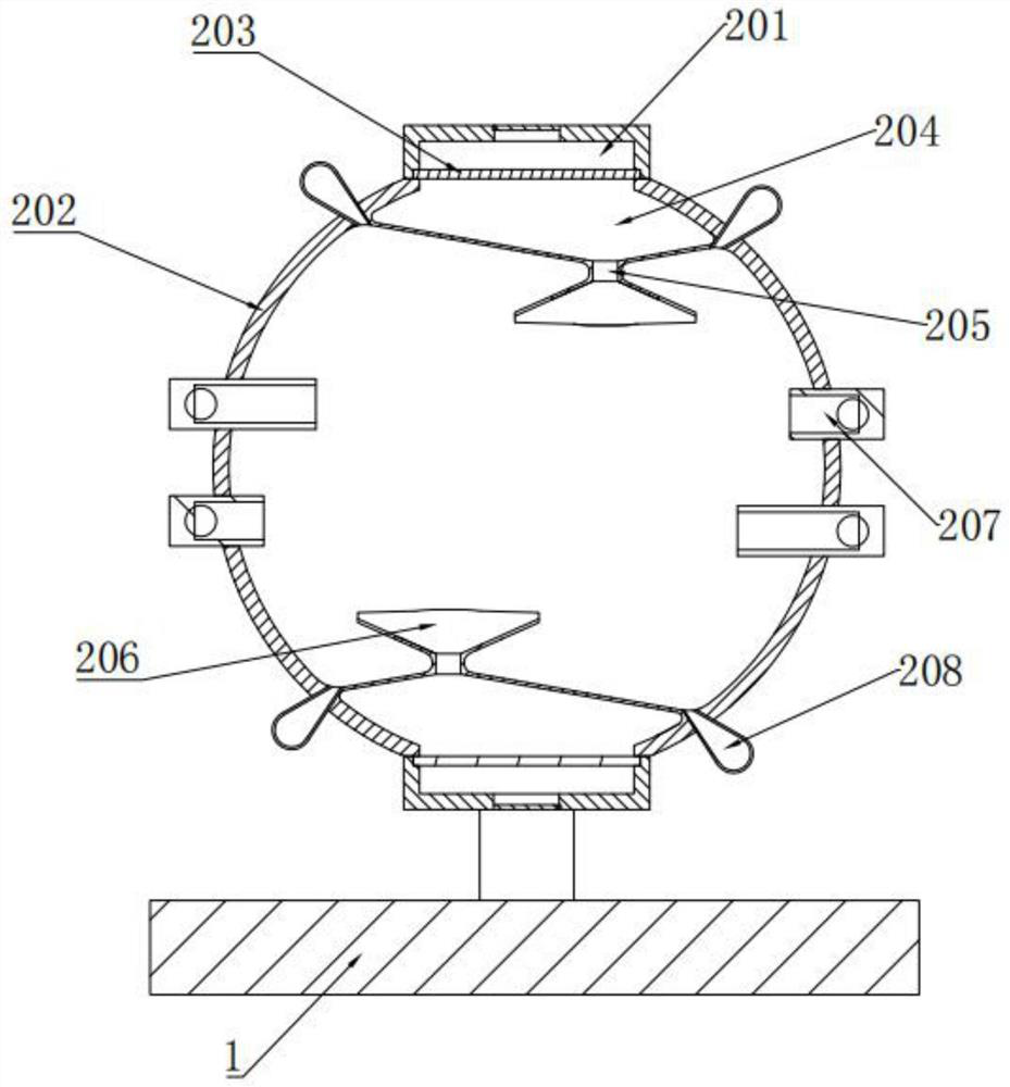
[0019] Specifically, the working bin 2 is a cylindrical hollow structure, the outer part of the working bin 2 is provided with an insulating layer 202, the upper and lower sides of the working bin 2 are symmetrical structures, the working bin 2 is equipped with a storage bin 201, and the A movable partition 203 is installed under the storage bin 201, and a flow chamber 204 is installed under the partition 203. The bottom of the flow chamber 2...


PUM


Abstract

The invention discloses a welding flux drying machine. The welding flux drying machine comprises a base and a working bin, wherein a supporting seat is fixed to the left side of the base, a hot air blower is connected to the supporting seat, an exhaust fan is further arranged on the supporting seat, a motor is fixed to the right side of the base, a control bin is arranged below the motor, the working bin is installed between the motor and the hot air blower, the motor can drive the working bin to rotate, and the hot air blower is fixed to the left side of the working bin. In order to solve the problems of welding flux drying, granularity screening and the like, the invention provides the welding flux drying machine.

Description

technical field [0001] The invention belongs to the field of dryers, in particular to a flux dryer. Background technique [0002] In my country's metal structure manufacturing industry, especially in the production process of shipbuilding, boilers, locomotives, hoisting machinery, etc., the submerged arc welding process occupies a large proportion, especially for the factory flow operation, the submerged arc process is characterized by its high The characteristics of high efficiency, stable quality, and safety guards have been widely used. [0003] At present, the submerged arc welding process is mainly used in the welding production of low-carbon steel and low-alloy steel structures. In the welding process of this type of steel, the most prominent problem is delayed crack generation, because of its characteristic of delayed fracture, Often lead to more serious accidents. [0004] The moisture content in the welding material is one of the main causes of cracks. Therefore, w...

Claims


Application Information

Patent Timeline
IPC IPC(8): F26B17/12F26B21/00F26B25/00B07B4/02
CPCF26B17/122F26B21/004F26B25/002B07B4/02Y02P70/10
Inventor 胡伟丁攀登肖卫
Owner 泰和县鹏翔挂车制造有限公司
Learn More