Method and device for monitoring closing state of disconnecting link,equipment and storage medium

A knife switch and status technology, applied in the field of substations, can solve problems such as inaccurate switch status indication, difficulty in operating personnel, and misjudgment of knife switch status, so as to improve safety and reliability, reduce equipment operation risks, and improve The effect of accuracy

Active Publication Date: 2021-11-02
GUANGDONG POWER GRID CO LTD +1
View PDF11 Cites 2 Cited by
  • Summary
  • Abstract
  • Description
  • Claims
  • Application Information

AI Technical Summary

Problems solved by technology

[0003] At present, the monitoring of the closing state of the knife switch in the existing substation mainly relies on the experience of the operator to observe, and there are the following problems: 1) The operator mainly observes and judges the status of the limit screw and the opening and closing indicator ball, so that To determine the opening and closing status of the knife switch, the judgment result is greatly affected by the observation angle and the site environment; The state deviation of the switch is relatively small, and it is usually difficult for the operator to notice it obviously, and it is easy to misjudge the state of the knife switch; 3) The connecting rod equipment such as the limit screw and the opening and closing indicator ball are affected by the operating life of the equipment, and it is easy to produce Mechanical looseness may easily cause inaccurate status indication of the knife switch

Method used


Image

  • Method and device for monitoring closing state of disconnecting link,equipment and storage medium
  • Method and device for monitoring closing state of disconnecting link,equipment and storage medium
  • Method and device for monitoring closing state of disconnecting link,equipment and storage medium

Examples


Embodiment 1

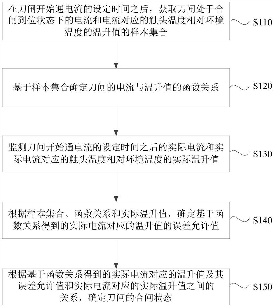
[0056] figure 1 It is a flowchart of a method for monitoring the closing state of a knife switch provided by the present invention. This embodiment is applicable to monitoring the closing state of a knife switch. This method can be executed by a state monitoring device for a knife switch. The device can Realized by means of software and / or hardware, the device can be configured in electronic equipment, such as a server or a terminal device, and a typical terminal device includes a mobile terminal, specifically a mobile phone, a computer, or a tablet computer. Such as figure 1 As shown, the method may specifically include:

[0057] S110. After the set time for the knife switch to start passing current, acquire a sample set of the current when the knife switch is in the fully closed state and the temperature rise value of the contact temperature relative to the ambient temperature corresponding to the current.

[0058] Wherein, the closing status of the knife switch includes a...

Embodiment 2

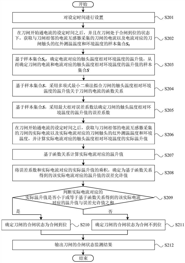
[0114] figure 2 It is a flow chart of another method for monitoring the closing state of a knife switch provided by the present invention. On the basis of the above embodiments, this embodiment further optimizes the method for monitoring the closing state of a knife switch. Such as figure 2 As shown, the method may specifically include:

[0115] S201, setting the set time.

[0116] Wherein, the set time refers to the start time for monitoring the closing state of the knife switch, and the specific time for monitoring the closing state of the knife switch refers to the time after the set time when the knife switch starts to pass current. By setting the time length of the set time, the specific time for monitoring the closing state of the knife switch can be determined.

[0117] S202. After the set time for the switch to start passing current, and when the switch is in the closed state, obtain the current of the switch and the contact of the switch corresponding to the curr...

Embodiment 3

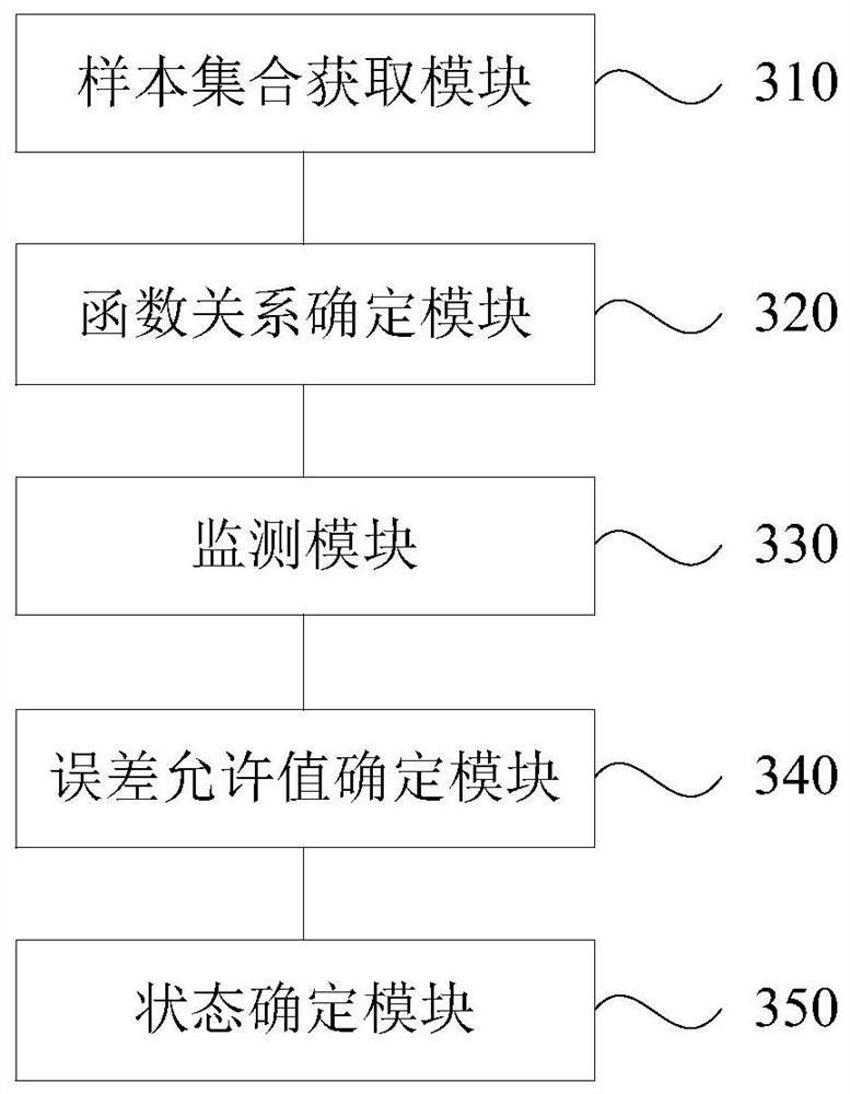
[0149] image 3 It is a structural diagram of a device for monitoring the closing state of a knife switch provided by the present invention. This embodiment is applicable to monitoring the closing state of a knife switch. The device for monitoring the closing state of a knife switch provided by the present invention can execute the method for monitoring the closing state of a knife switch provided in any embodiment of the present invention, and has corresponding functional modules and beneficial effects for executing the method. Such as image 3 As shown, the device specifically includes a sample set acquisition module 310, a functional relationship determination module 320, a monitoring module 330, an error tolerance value determination module 340 and a state determination module 350, wherein:

[0150] The sample set acquisition module 310 is used to obtain a sample set of the current and the temperature rise of the contact temperature relative to the ambient temperature whe...


PUM


Abstract

The invention discloses a method and a device for monitoring the closing state of a disconnecting link, equipment and a storage medium. The method for monitoring the state of the disconnecting link comprises the following steps: after a set time when the disconnecting link begins to be electrified, acquiring a sample set of current when the disconnecting link is in a closing in-place state and a temperature rise value of contact temperature corresponding to the current relative to environment temperature; determining a function relationship between the current and the temperature rise value of the disconnecting link based on the sample set; monitoring the actual current after the set time when the disconnecting link begins to be electrified and the actual temperature rise value of the contact temperature corresponding to the actual current relative to the environment temperature; according to the sample set, the function relationship and the actual temperature rise value, determining an error allowable value of the temperature rise value corresponding to the actual current obtained based on the function relationship; and determining the closing state of the disconnecting link according to the relationship between the temperature rise value corresponding to the actual current obtained based on the function relationship, the error allowable value of the temperature rise value and the actual temperature rise value corresponding to the actual current. According to the scheme, the accuracy of monitoring the closing state of the disconnecting link can be improved.

Description

technical field [0001] The invention relates to the technical field of substations, in particular to a method, device, equipment and storage medium for monitoring the closing state of a knife switch. Background technique [0002] Knife switch (isolating switch) is a kind of power equipment switch. The opening and closing of the knife switch are the key points and dangerous points in the switching operation of power transformation operation. Whether the opening and closing is in place directly affects the power grid , equipment and personal safety. In recent years, the power grid and personal safety accidents caused by the failure of the opening and closing of the knife switch account for the vast majority of the safety accidents in the power grid operation. Generally speaking, the opening of the knife switch is usually easier to observe. Compared with the opening of the knife switch, due to the secrecy of the closing of the knife switch, it is often difficult to directly o...

Claims


Application Information

Patent Timeline
Patent Type & Authority Applications(China)
IPC IPC(8): G01R31/327G01K13/00G06F17/15
CPCG01R31/327G01K13/00G06F17/15
Inventor 刘泽槐蒋紫薇姚俊钦李帝周
Owner GUANGDONG POWER GRID CO LTD
Why Eureka
Try Eureka