Infrared sub-pixel polarized light imaging device and imaging method

An imaging device and polarized light technology, applied in optics, image communication, optical components, etc., can solve problems such as resolution reduction, resolution difficulty, signal crosstalk, etc., to reduce pixel pitch, reduce overall cost, and reduce The effect of size and cost

Pending Publication Date: 2021-11-02
XINFOO SENSOR TECH CO LTD
View PDF0 Cites 0 Cited by
  • Summary
  • Abstract
  • Description
  • Claims
  • Application Information

AI Technical Summary

Problems solved by technology

[0002] In order to obtain infrared polarized light images, a layer of polarizers is usually added above the acquisition unit of traditional infrared polarized light imaging sensors. For example, N polarizers with different angles are placed on a single pixel, and each group of N pixels is used as one computing unit, which results in a resolution down to 1 / N
[0003] Therefore, in order to improve the resolution, it is necessary to increase the number of pixels in the unit optical area, that is, to reduce the size of the pixels, but when the pixels are reduced to a certain size, due to the constraints of the diffraction limit, the adjacent pixels will be separated. The signal produces crosstalk, and the diffraction limit is that when a beam of light is focused on a single pixel, it will rapidly defocus on the surface of the pixel due to diffraction, forming a light cone section, that is, the Airy disk, and the size of the pixel should not be smaller than Airy disk radius, therefore, it is extremely difficult to maintain resolution by increasing the number of pixels per unit optical area

Method used

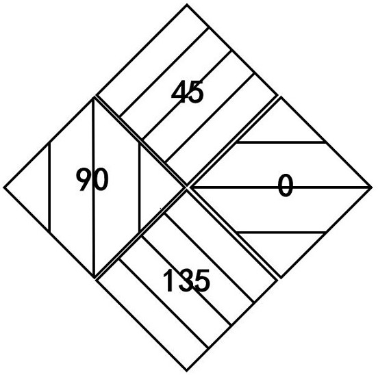
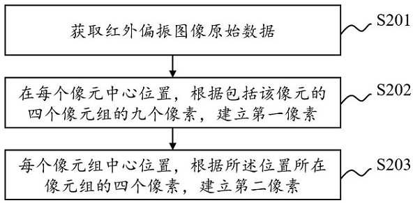
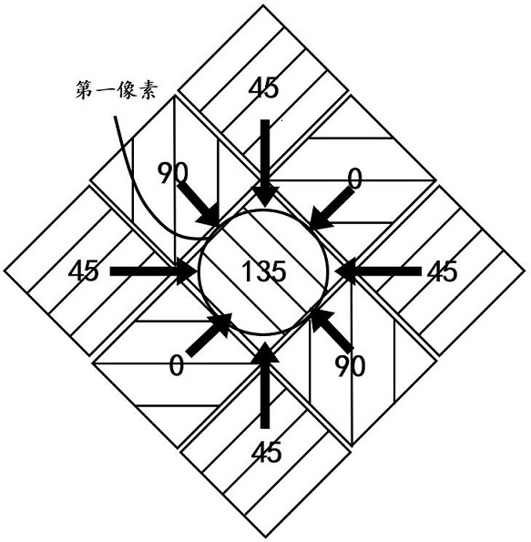

Image

  • Infrared sub-pixel polarized light imaging device and imaging method
  • Infrared sub-pixel polarized light imaging device and imaging method
  • Infrared sub-pixel polarized light imaging device and imaging method

Examples


Embodiment Construction

[0031] In order to make the above objects, features and advantages of the present invention more comprehensible, specific implementations of the present invention will be described in detail below in conjunction with the accompanying drawings.

[0032] In the following description, a lot of specific details are set forth in order to fully understand the present invention, but the present invention can also be implemented in other ways different from those described here, and those skilled in the art can do it without departing from the meaning of the present invention. By analogy, the present invention is therefore not limited to the specific examples disclosed below.

[0033] It should be noted that in this article, relational terms such as first and second etc. are only used to distinguish one entity or operation from another entity or operation, and do not necessarily require or imply that there is a relationship between these entities or operations. There is no such actual...


PUM


Abstract

The invention discloses an infrared sub-pixel polarized light imaging device and an imaging method. On the basis of using a staggered rhombus array mode, pixel pitch can be greatly reduced by reconstructing pixels containing polarization information of different polarization angles. Due to the fact that the size of the pixel pitch determines resolving power, on the premise that the resolution ratio is not changed, the optical area is greatly reduced, the size of the sensor is reduced, the size and the cost of the lens are reduced, and the cost of the whole machine is greatly reduced.

Description

technical field [0001] The present application relates to an infrared imaging device, in particular to an infrared sub-pixel polarized light imaging device and an imaging method. Background technique [0002] In order to obtain infrared polarized light images, a layer of polarizers is usually added above the acquisition unit of traditional infrared polarized light imaging sensors. For example, N polarizers with different angles are placed on a single pixel, and each group of N pixels is used as One compute unit, which would result in a resolution down to 1 / N. [0003] Therefore, in order to improve the resolution, it is necessary to increase the number of pixels in the unit optical area, that is, to reduce the size of the pixels, but when the pixels are reduced to a certain size, due to the constraints of the diffraction limit, the adjacent pixels will be separated. The signal produces crosstalk, and the diffraction limit is that when a beam of light is focused on a single ...

Claims


Application Information

Patent Timeline
Patent Type & Authority Applications(China)
IPC IPC(8): H04N5/369H04N5/33G02B27/28
CPCH04N5/33G02B27/28H04N25/70
Inventor 赵照林晓东
Owner XINFOO SENSOR TECH CO LTD
Why Eureka
Try Eureka