
Efficient tea drying equipment for tea processing

A technology for baking tea and equipment, which is applied in tea processing before extraction, conveyor objects, transportation and packaging, etc. It can solve the problems of inability to achieve one-time drying and drying treatment, inability to continuously and efficiently make tea, and high energy consumption. Achieve the effect of reducing the time of manual preparation, improving the efficiency of tea making and increasing the contact area

Inactive Publication Date: 2021-11-05
张强
View PDF0 Cites 0 Cited by
  • Summary
  • Abstract
  • Description
  • Claims
  • Application Information

AI Technical Summary

Problems solved by technology

[0003] However, in the existing tea-making industry, most of the equipment used still needs to manually observe the color of the tea to make tea, which cannot achieve one-time drying and drying treatment, and cannot continuously and efficiently make tea. much, so for higher energy consumption, this will increase the cost substantially

Method used


Image

  • Efficient tea drying equipment for tea processing
  • Efficient tea drying equipment for tea processing
  • Efficient tea drying equipment for tea processing

Examples


Embodiment 1

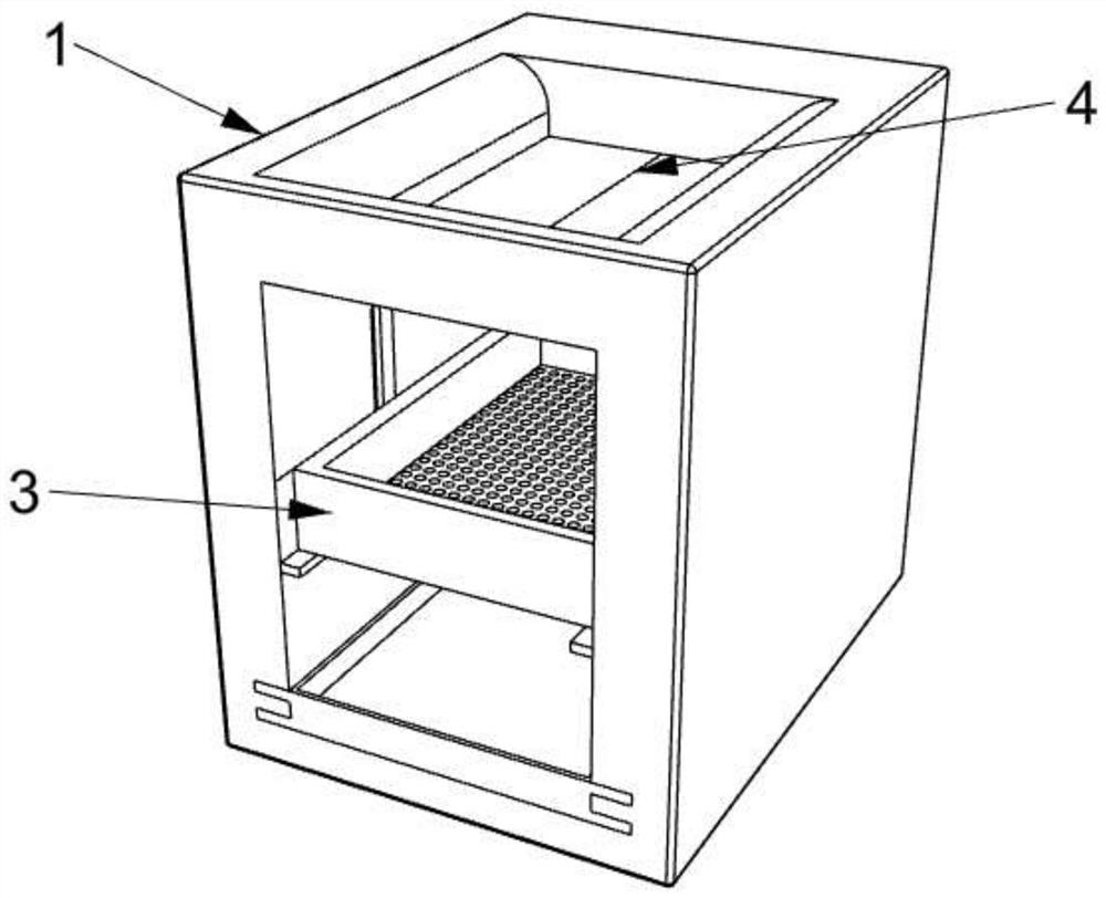
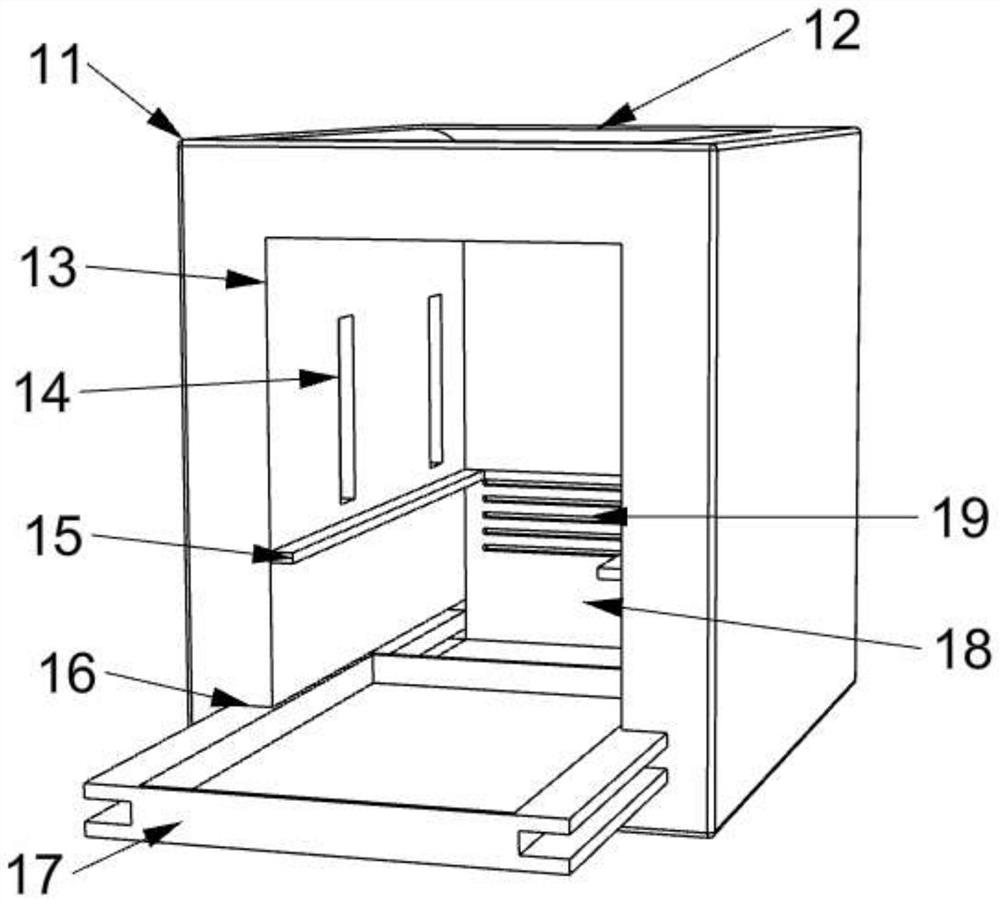
[0033] see Figure 1-5 , in an embodiment of the present invention, a high-efficiency tea-baking equipment for tea processing includes a tea-baking equipment part 1, and the tea-baking equipment part 1 includes a device body 11, a tea tank 12, a tea-baking chamber 13, a movable tank 14, a sliding Plate 15, engaging groove 16, charcoal fire insert 17, baffle plate 18 and air outlet 19;

[0034] The middle part of the upper end of the device body 11 is provided with a tea trough 12, the middle part of the device body 11 is provided with a tea-baking chamber 13, and several groups of movable grooves 14 are arranged symmetrically on the left and right sides of the tea-baking chamber 13, and the middle parts of the left and right walls of the tea-baking chamber 13 are fixed, installed and slidable Plate 15, engaging grooves 16 are symmetrically set on the left and right side walls of the lower part of the tea baking chamber 13, and a charcoal fire insert 17 is arranged between the ...

Embodiment 2

[0046] see Image 6 The difference from Example 1 is that a tea trough 319 is set on the upper side of the front end of the tea making piece 315, and the inner side of the tea trough 319 is slope-shaped, and a collecting plate 320 is arranged inside the tea making piece 315. The cross section of the collecting plate 320 is trapezoidal, and the front end of the collecting plate 320 is fixed with a connecting rod handle 321;

[0047] When in use, when the tea leaves are dried and baked, the collecting plate 320 is used to slide in the tea making piece 315, and the inclined surface at the lower end of the collecting plate 320 and the lower end of the tea outlet groove 319 are forced to limit, so that the dried tea leaves can be collected quickly.


PUM


Abstract

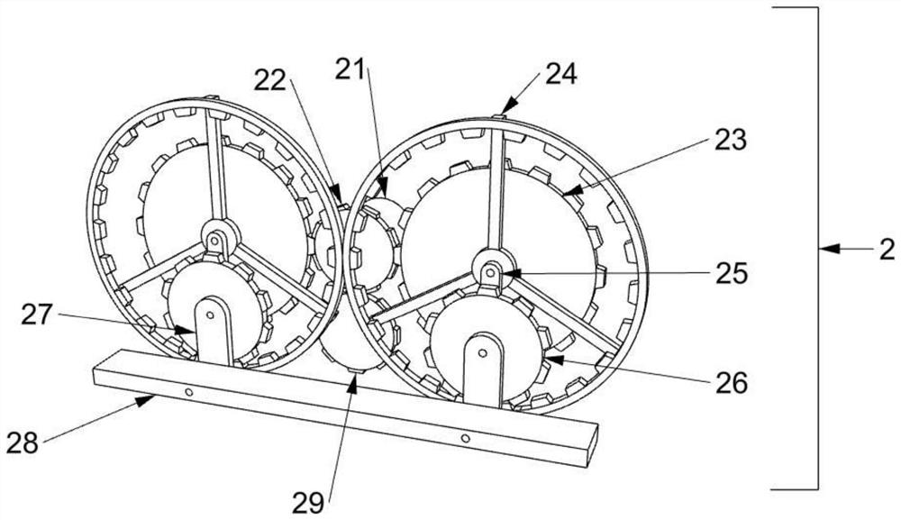
The invention discloses efficient tea drying equipment for tea processing. The efficient tea drying equipment for tea processing comprises a tea drying equipment part, wherein the tea drying equipment part comprises an equipment body, a tea placing groove, a tea drying cavity, a plurality of groups of movable grooves, sliding plates, clamping grooves, a charcoal fire placing part, a baffle plate and an air outlet, the tea placing groove is formed in the middle of the upper end of the equipment body, and the tea drying cavity is formed in the middle of the equipment body; and the movable grooves are symmetrically formed in the left and right sides of the tea drying cavity, and the sliding plates are fixedly mounted in the middles of the wall surfaces of the left side and the right side of the tea drying cavity. When the efficient tea drying equipment is used, rotating discs are driven by driven teeth to rotate, a driven piece II is driven by fixing rods to rotate, linkage wheels are driven by small fixing wheels to slowly rotate, then a fixing block continuously triggers a rotating rod in a timing mode, a tea placing bottom plate part rotates towards the lower end, tea leaves are put in the timing mode, and the time for manual tea putting is shortened.

Description

technical field [0001] The invention relates to a tea-baking equipment, in particular to a high-efficiency tea-baking equipment for tea processing. Background technique [0002] During the processing of tea leaves, roasting is required, and good withering is the prerequisite for the formation of high-quality tea leaves. Put the withered tea leaves in a bamboo sieve and knead them back and forth, so that the edges of the leaves are rubbed, the leaf edge cells are damaged, and the water is lost after spreading. The polyphenols in the leaves are gradually oxidized under the action of enzymes, forming the unique tea quality. [0003] However, in the existing tea-making industry, most of the equipment used still needs to manually observe the color of the tea to make tea, which cannot achieve one-time drying and drying treatment, and cannot continuously and efficiently make tea. Much, so for higher energy consumption, this will substantially increase the cost. Therefore, those ...

Claims


Application Information

Patent Timeline
Patent Type & Authority Applications(China)
IPC IPC(8): A23F3/06B65G47/74
CPCA23F3/06B65G47/74
Inventor 张强
Owner 张强
Learn More