Internal fixation eye bag drag hook for releasing orbital septum fat through conjunctival approach
A technology for fixing eyes and orbits, which is applied in the field of medical devices and can solve problems such as smaller suture space, unfavorable incision pulling, unfavorable surgery, etc.
- Summary
- Abstract
- Description
- Claims
- Application Information
AI Technical Summary
Problems solved by technology
Method used
Image
Examples
Embodiment 1
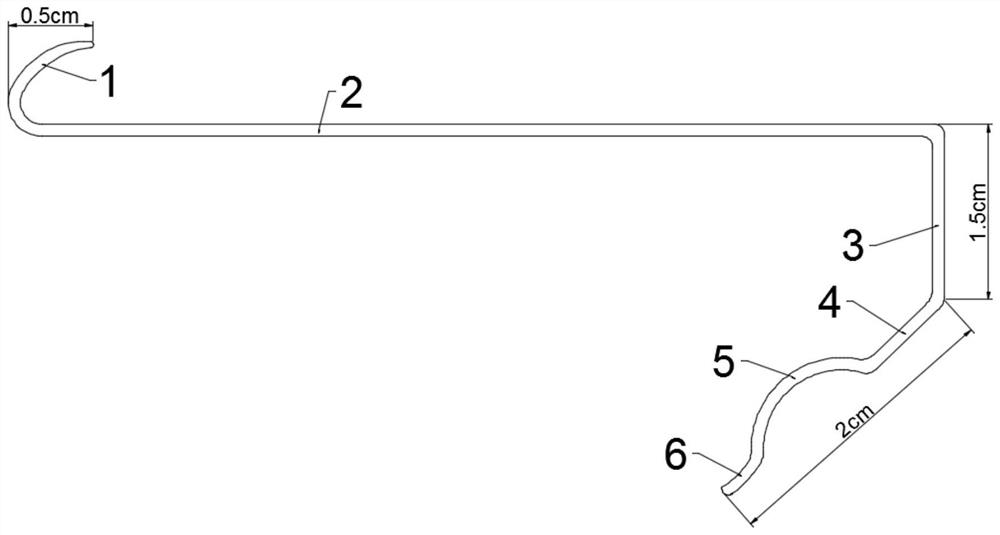
[0022] Embodiment 1 is basically as attached figure 1 Shown: Transconjunctival approach to orbital septal fat release internal fixation pouch retractor, including handle 2 and short retractor 1 and long retractor located at both ends of handle 2, the handle 2, short retractor 1 and long retractor are integrally formed; the extension direction of short retractor 1 Located above the handle 2, the extension direction of the long retractor is located below the handle 2, the width of the short retractor 1, handle 2 and long retractor is 0.6CM, and the width direction of the long retractor, short retractor 1 and handle 2 is parallel; the short retractor 1 It is arc-shaped, the length projection distance of the short hook 1 is 0.5CM, and the inner concave surface of the short hook 1 faces the handle 2; the long hook includes an integrally formed connecting piece 3, lower pressing piece 4, expanding piece 5 and positioning piece 6, and pressing down The two ends of the piece 4 are res...
Embodiment 2
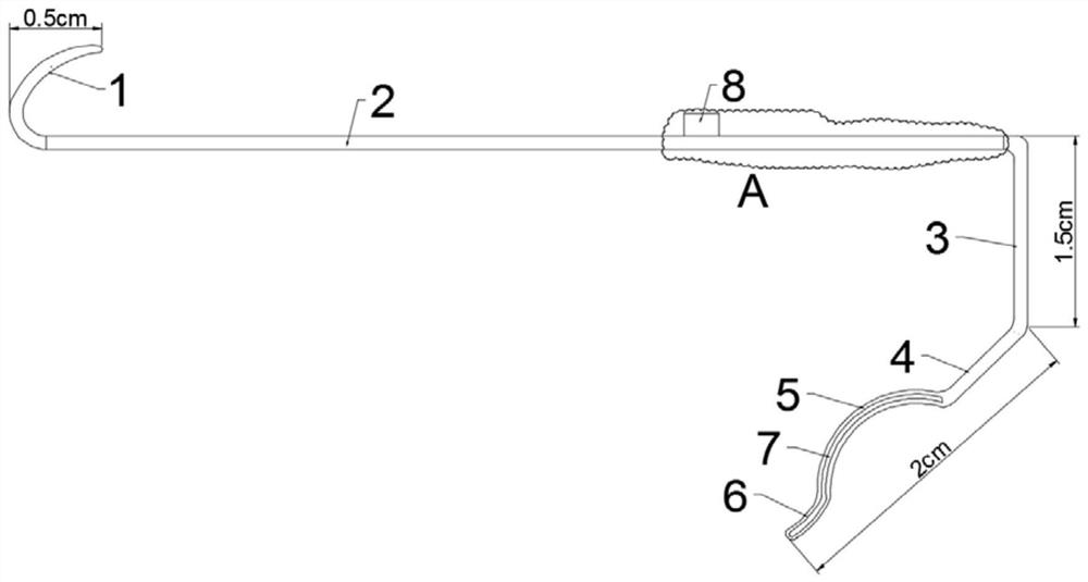
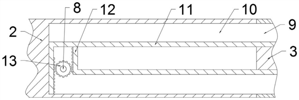
[0023] Embodiment 2 is basically as attached Figure 2~3 As shown, the intra-conjunctival orbital septum fat release internal fixation eye bag retractor is only different from Embodiment 1 in that a cavity 10 is provided in the handle 2, and an adjustment mechanism is provided in the cavity 10, and the adjustment mechanism includes gears 13 and Two sets of sliding assemblies, the handle 2 is connected with a knob 8 for rotation, and the knob 8 is located on the upper surface of the handle 2; the gear 13 is fixedly connected to the knob 8, and the sliding assembly includes a connecting rod 11 and a driving rod 12, and the connecting rod 11 and the driving rod 12 Forming an "L" shape, two drive rods 12 are respectively located on both sides of the gear 13, and the extension directions of the two drive rods 12 are opposite. On the connecting rod 11 of the sliding assembly; the free end of the driving rod 12 of another set of sliding assembly is held against the side wall of the c...
PUM
 Abstract
Description
Claims
Application Information
 - R&D
- Intellectual Property
- Life Sciences
- Materials
- Tech Scout
- Unparalleled Data Quality
- Higher Quality Content
- 60% Fewer Hallucinations
Browse by: Latest US Patents, China's latest patents, Technical Efficacy Thesaurus, Application Domain, Technology Topic, Popular Technical Reports.
© 2025 PatSnap. All rights reserved.Legal|Privacy policy|Modern Slavery Act Transparency Statement|Sitemap|About US| Contact US: help@patsnap.com


