
A continuously adjustable integrated anti-clogging screen device

An anti-clogging and adjustable technology, applied in chemical instruments and methods, fixed filter element filters, separation methods, etc., can solve the problems of increasing auxiliary operation time, reducing repair efficiency, and reducing porosity, so as to reduce auxiliary operation time , Enhance the dynamic adaptability and improve the confining pressure strength

Active Publication Date: 2022-06-24
XIAN RES INST OF CHINA COAL TECH& ENG GROUP CORP
View PDF6 Cites 0 Cited by
  • Summary
  • Abstract
  • Description
  • Claims
  • Application Information

AI Technical Summary

Problems solved by technology

During the working process, the screen pipe needs to bear the high confining pressure from the formation. Therefore, in order to ensure a high working strength, the current screen pipe is mainly manufactured through winding, binding, welding, laser cutting and other manufacturing processes, but the porosity of the screen pipe after manufacture is It is a fixed value and cannot be properly adjusted according to changes in the environment to achieve the optimal effect
[0003] At the same time, after a period of use, impurities in the soil will be deposited in the pores of the screen, resulting in blockage of the screen and a decrease in porosity, which will affect the smooth development of hydrodynamic circulation and repair operations
At this time, it is necessary to regularly lift the screen from the bottom of the hole for maintenance and cleaning operations, which greatly increases the auxiliary operation time and reduces the repair efficiency

Method used


Image

  • A continuously adjustable integrated anti-clogging screen device
  • A continuously adjustable integrated anti-clogging screen device
  • A continuously adjustable integrated anti-clogging screen device

Examples


Embodiment 1

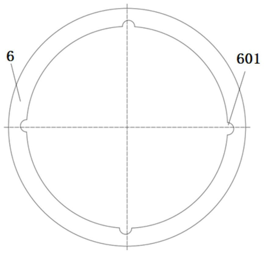
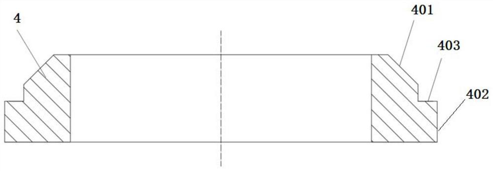
[0040] The present embodiment provides a continuously adjustable integrated anti-clogging screen device, which includes a screen frame 1 and cylindrical upper screen joints 2 and lower screen joints 3 arranged at both ends of the screen frame 1 and coaxial with each other. ; Screen skeleton 1 includes a plurality of axial skeleton lines 101, oblique skeleton lines 102 and adjustable skeleton lines 103.

[0041] The axial skeleton line 101 is connected between the upper screen joint 2 and the lower screen joint 3 and is parallel to the axes of the two, and a plurality of axial skeleton lines 101 are evenly distributed along the circumferential direction to surround the upper screen joint 2 and the lower screen joint. The screen joint 3 is a coaxial cylindrical frame; the oblique frame line 102 is connected between the upper screen joint 2 and the lower screen joint 3 and is fixed on the cylindrical frame obliquely, and the plurality of inclined frame lines 102 are uniform in the...

Embodiment 2

[0054] This embodiment provides a method for manually adjusting the porosity of a continuously adjustable integrated anti-clogging screen device. The method is implemented by the screen device in Embodiment 1. The initial state of the screen device is: under the action of a compression spring , the adjusting ring is close to the adjusting nut, and the adjusting nut is rotated to set an initial position for the adjusting ring in the axial direction. At the position of the minimum outer diameter, the axial support rod is closest to the center axis X of the screen device in the radial direction, and the adjustable skeleton line fixed with the axial support rod by welding with the radial support rod is also radially away from the center. The axis X is the closest, on the contrary, the circular section of the adjustable skeleton line is the farthest from the section of the oblique skeleton line on both sides, and the porosity of the screen device also reaches the maximum at this tim...

Embodiment 3

[0059] This embodiment provides a mechanical automatic adjustment method for the porosity of a continuously adjustable integrated anti-clogging screen device. The manual adjustment method in Embodiment 2 is suitable for determining the optimal porosity of the screen during operation according to site data and working conditions. , If it is necessary to continuously adjust the porosity of the screen in real time during the operation, it is necessary to use mechanical automatic adjustment,

[0060] The porosity mechanical automatic adjustment method includes the following steps:

[0061] Step b1, such as Figure 7 As shown, the upper screen joint of the screen device is connected with the outer pipe 8 of the upper well string, and the lower screen joint is connected with the outer pipe 9 of the lower well string and placed in the working position in the well, inside the outer pipe 8 of the upper well string. A driving rod body 10 with a central through hole is provided. The low...


PUM


Abstract

The invention discloses a continuously adjustable integrated anti-clogging screen device, which comprises a screen frame and upper screen joints and lower screen joints arranged at both ends of the screen frame; the screen frame includes a plurality of axial frame lines, oblique Axial skeleton lines and adjustable skeleton lines; the axial skeleton lines are connected between the upper screen joint and the lower screen joint and are parallel to the axes of the two, and a plurality of axial skeleton lines are evenly distributed along the circumference to surround the upper screen. The mesh joint and the lower screen joint are coaxial cylindrical skeletons; the oblique skeleton lines are obliquely fixed on the cylindrical skeleton and a plurality of oblique skeleton lines are evenly distributed along the circumference, and there are sets between adjacent two oblique skeleton lines An adjustable skeleton wire running in the same direction as the oblique skeleton wire; the adjustable skeleton wire can move radially to change the gap between the adjustable skeleton wire and the oblique skeleton wires on both sides so as to adjust the porosity of the screen mesh skeleton. The sieve porosity of the present invention can be adjusted in real time according to the change of working conditions, and has anti-clogging function at the same time, which greatly improves the efficiency of repair work.

Description

technical field [0001] The invention belongs to the technical field of water resources restoration and filtering equipment, and in particular relates to a continuously adjustable integrated anti-clogging screen device. Background technique [0002] In the water well industry, the screen pipe, also known as the water filter pipe, is a key component of water resource filtration and contaminated site remediation equipment. The screen is usually located in the middle and lower part of the repair equipment, and is mainly used to filter and block sediment and provide a channel for the hydrodynamic circulation. During the working process, the screen tube needs to withstand high confining pressure from the formation. Therefore, in order to ensure high working strength, the current screen tube is mainly manufactured by winding, binding, welding, laser cutting and other manufacturing processes, but the porosity of the screen tube after manufacturing is completed. As a fixed value, it...

Claims


Application Information

Patent Timeline
Patent Type & Authority Patents(China)
IPC IPC(8): B01D29/35
CPCB01D29/35B01D29/111
Inventor 田东庄田宏杰董萌萌马宇王传留马少明陈彦宇居培
Owner XIAN RES INST OF CHINA COAL TECH& ENG GROUP CORP
Learn More