
Clamp for splicing power battery cells

A power battery and cell technology, which is applied in battery pack components, circuits, hand-held tools, etc., can solve the problem of not reaching the splicing of multiple single cells.

Pending Publication Date: 2021-11-05
STATE GRID ZHEJIANG ELECTRIC VEHICLE SERVICE CO LTD +1
View PDF7 Cites 0 Cited by
  • Summary
  • Abstract
  • Description
  • Claims
  • Application Information

AI Technical Summary

Problems solved by technology

There are also public technologies for positioning batteries in the prior art, but most of them clamp the batteries for further processing of the batteries, and do not achieve the purpose of stitching multiple single batteries together

Method used


Image

  • Clamp for splicing power battery cells
  • Clamp for splicing power battery cells
  • Clamp for splicing power battery cells

Examples


Embodiment Construction

[0027] The following will clearly and completely describe the technical solutions in the embodiments of the application with reference to the drawings in the embodiments of the application. Apparently, the described embodiments are only some of the embodiments of the application, not all of them. Based on the embodiments in this application, all other embodiments obtained by persons of ordinary skill in the art without making creative efforts belong to the scope of protection of this application.

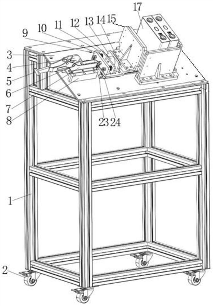
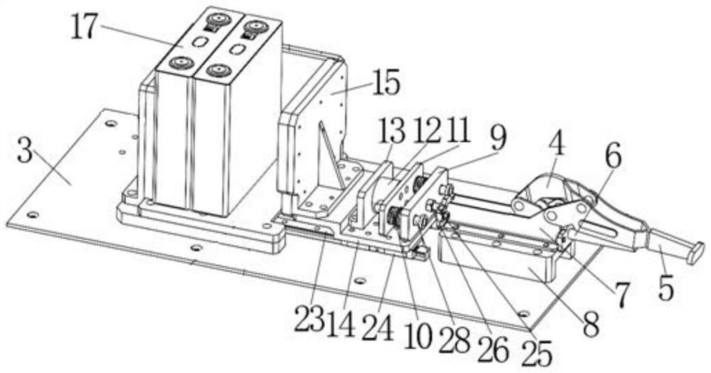
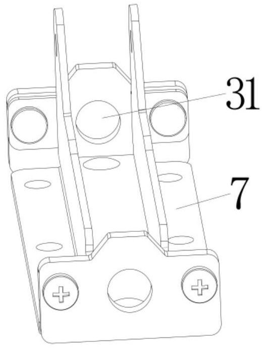
[0028] Please refer to Figure 1-4 , figure 1 It is a schematic diagram of the overall structure of a specific embodiment of the present invention; figure 2 for figure 1 Schematic diagram of the workpiece structure on the middle workbench; image 3 for figure 1 Schematic diagram of the structure of the middle limit slide rail; Figure 4 for figure 1 An enlarged schematic view of the middle connecting rod part.

[0029] The jig for splitting power battery cells provided by th...


PUM


Abstract

The invention discloses a clamp for splicing power battery cells. The clamp comprises an accommodating part for accommodating a plurality of battery cells, the accommodating part is provided with a box body with an open structure, and one side of the box body being provided with a movable push plate; a driving part is arranged at the outer side of the movable push plate, and the driving part can drive the movable push plate to move towards the direction of the battery cells; a movable pressure sensor and a pressure buffering part are sequentially arranged between the movable push plate and the driving part; the pressure buffering part is close to one side of the driving part, and a first vertical supporting plate is arranged between the pressure buffering part and the driving part; and the movable push plate, the pressure sensor, the pressure buffering part and the first vertical supporting plate are all arranged on a support, and the support is arranged on a self-locking guide rail in a sliding manner. The clamp can accurately provide required pressing force, and the pressing force can be kept unchanged after the battery cells are spliced and pressed.

Description

technical field [0001] The invention relates to the technical field of battery processing, in particular to a jig for assembling power battery cells. Background technique [0002] A battery refers to a cup, tank, or other container or part of a composite container that contains an electrolyte solution and a metal electrode to generate current. It is a device that can convert chemical energy into electrical energy. It has a positive pole and a negative pole. The power battery is the power source that provides the power source for the tool, and mostly refers to the battery that provides power for electric vehicles, electric trains, electric bicycles, and golf carts. A cell refers to a single electrochemical cell containing positive and negative electrodes, which is generally not used directly. The difference is that the battery contains a protective circuit and a casing, which can be used directly. [0003] During the assembly and processing of the power battery, the single ...

Claims


Application Information

Patent Timeline
Patent Type & Authority Applications(China)
IPC IPC(8): B25B27/02B25B11/02H01M50/204H01M50/244H01M50/264
CPCB25B27/02B25B11/02H01M50/204H01M50/244H01M50/264Y02E60/10
Inventor 李波王宁李梁李媛陈婧韵王天浩李艳薇潘毓庞倩怡
Owner STATE GRID ZHEJIANG ELECTRIC VEHICLE SERVICE CO LTD
Learn More