Gear shaping machine tool rest body front-back swing guiding mechanism

A guide mechanism, gear shaper technology, applied in the direction of gear cutters, gear teeth, mechanical equipment, etc., can solve the problems of tool holder body vibration, cutting rigidity, affecting the tool shaft of the gear shaper, etc., to improve the matching accuracy and eliminate the guide. Clearance, friction and wear reduction effect

Active Publication Date: 2016-07-06
宜昌长机科技有限责任公司
View PDF9 Cites 1 Cited by
  • Summary
  • Abstract
  • Description
  • Claims
  • Application Information

AI Technical Summary

Problems solved by technology

[0004] 1. The assembly process of the insert guide mechanism is complicated. In order to ensure sufficient guide rigidity and the tool holder body can swing flexibly, the sliding gap between the insert and the steel guide rail needs to be strictly controlled
[0005] 2. There is a guide gap after the insert guide mechanism has been running for a long time. The tool holder body will be affected by the cutting momentum during the gear shaping process, and the tool holder body will vibrate, which will affect the machining accuracy of the machine tool.
[0006] 3. It is inconvenient to adjust the gap of the guide mechanism of the insert, which requires professional and technical personnel to adjust, and it is difficult to maintain the machine tool later
[0007] 4. In the follow-up encountering the above situation, it is usually necessary to re-adjust the gap between the inserts. If the guide gap is too small, the tool holder body cannot swing flexibly. If the gap is too large, it will affect the cutting rigidity of the gear shaping machine tool shaft.

Method used


Image

  • Gear shaping machine tool rest body front-back swing guiding mechanism
  • Gear shaping machine tool rest body front-back swing guiding mechanism
  • Gear shaping machine tool rest body front-back swing guiding mechanism

Examples


Embodiment Construction

[0031] Embodiments of the invention will be further described below in conjunction with the accompanying drawings.

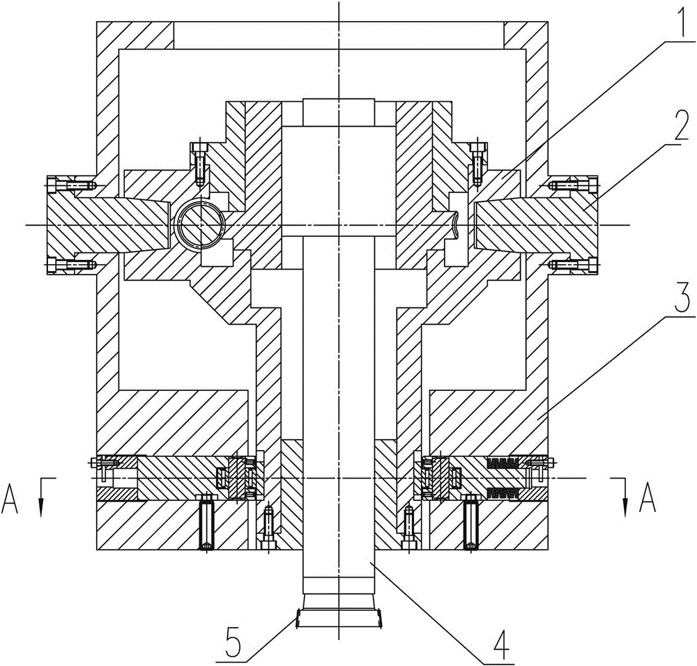
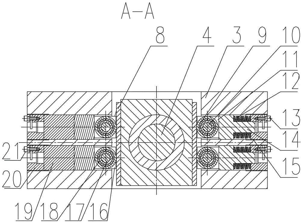
[0032] see figure 1 Or 3, a forward and backward swing guide mechanism of the tool rest body of the gear shaping machine, which includes a tool rest body 1, the tool rest body 1 is hinged on the column 3 through the ear shaft 2, and a main shaft 4 is installed inside the tool post body 1, and the main shaft 4 A gear shaper cutter 5 is installed at the end of the main shaft 4, and it is characterized in that: a crank linkage mechanism is installed on the top of the main shaft 4 to drive it to reciprocate up and down, and a longitudinal swing guide rail mechanism is installed at the position where the lower end of the main shaft 4 matches the column 3; The longitudinal swing guide rail mechanism includes a steel guide rail 8, which is fixedly installed on the tool holder body 1, and the right side of the steel guide rail 8 cooperates with the right side gap compe...


PUM


Abstract

The invention relates to a gear shaping machine tool rest body front-back swing guiding mechanism. The mechanism comprises a tool rest body. The tool rest body is hinged to a stand column through a trunnion. A spindle is installed in the tool rest body. A gear shaping cutter is installed at the tail end of the spindle. The mechanism is characterized in that a crank connecting rod mechanism is installed at the top of the spindle and is used for driving the spindle to reciprocate up and down; a longitudinal swing guide rail mechanism is installed in the position, matched with the stand column, of the lower end of the spindle; the longitudinal swing guide rail mechanism comprises a steel guide rail which is fixedly installed on the tool rest body; the right side face of the steel guide rail is matched with a right side backlash compensation device which is installed on the right side of the stand column; and the left side face of the steel guide rail is matched with a left side backlash compensation device which is installed on the left side of the stand column. The design requirement of tool rest body front-back swing cutter relieving backlash-free guide is met, and the advantages such as feasibility of the assembly process are achieved, so that the gear shaping machine tool rest body front-back swing guiding mechanism is especially suitable for existing gear shaping machine cutter relieving guide.

Description

technical field [0001] The invention belongs to the field of gear shaping machine devices, and in particular relates to a backlash-free guiding mechanism for a tool holder body of a gear shaping machine. Background technique [0002] Gear shaping is to use a gear shaping cutter on a gear shaping machine to process gears according to the principle of generating method. The gear shaper cutter is installed on the cutter shaft to make up and down reciprocating cutting motion through the crank mechanism. During the return stroke of the gear shaper cutter, the tool holder body swings back and forth to realize the retraction action of the gear shaper cutter. like figure 2 Shown is a structural schematic diagram of the front and rear swing guide mechanism of the existing gear shaping machine tool holder body, which is composed of inserts, adjustment pads, and steel guide rails, and cast iron inserts are used as the guide mechanism. According to the requirements of the guiding prec...

Claims


Application Information

Patent Timeline
Patent Type & Authority Applications(China)
IPC IPC(8): B23F23/00
CPCB23F23/00
Inventor 王维唐兆庆
Owner 宜昌长机科技有限责任公司
Why Eureka
Try Eureka