Roadbed widening method

A technology for roadbed and soil roadbed, applied in the directions of roads, filling, excavation, etc., can solve problems such as insufficient stability, and achieve the effects of fast construction, improved stability, and increased stability.

Pending Publication Date: 2021-11-05
SHANDONG UNIV +1
View PDF11 Cites 0 Cited by
  • Summary
  • Abstract
  • Description
  • Claims
  • Application Information

AI Technical Summary

Problems solved by technology

However, the inventors found that when the foam lightweight soil block subgrade is subjected to loads such as vehicle loads on the upper part, it will slide along the masonry surface, resulting in insufficient stability

Method used


Image

  • Roadbed widening method
  • Roadbed widening method
  • Roadbed widening method

Examples


Embodiment 1

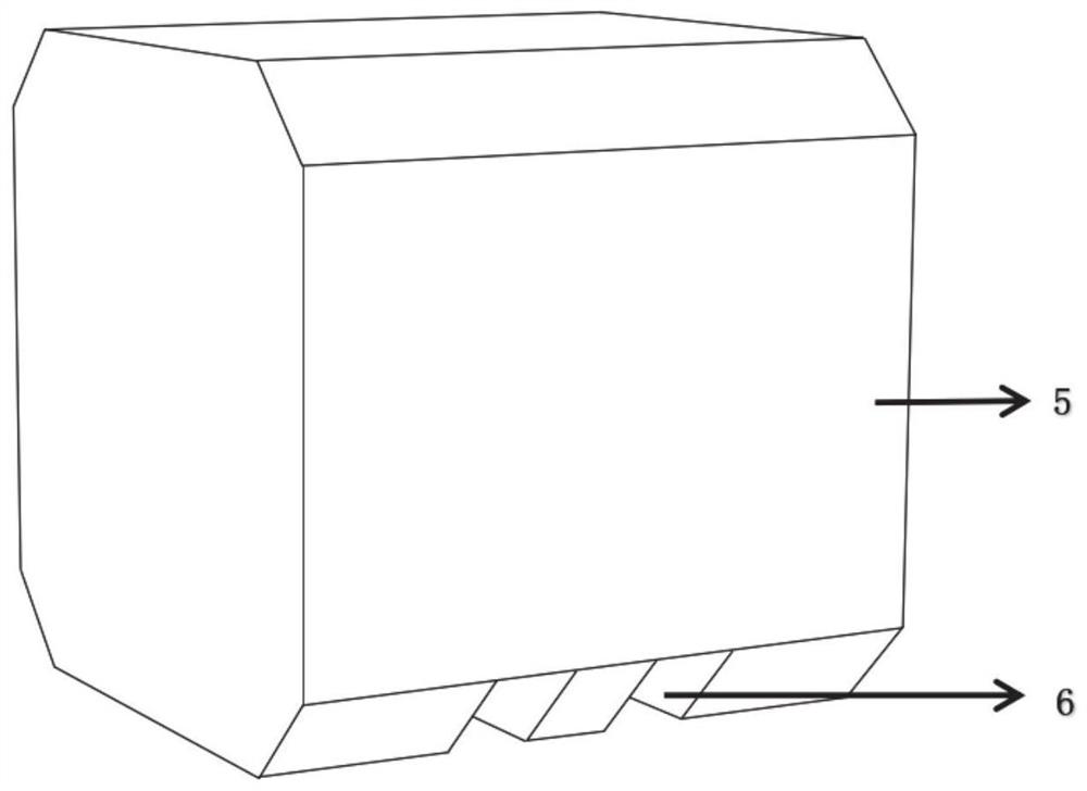
[0035] This embodiment discloses a roadbed widening method. The roadbed is widened by using a widening structure composed of foam light soil roadbed blocks and a retaining wall. The widening structure formed by the foam lightweight soil roadbed blocks is overlapped with the original roadbed to widen the original roadbed, and the retaining wall is in contact with the outer surface of the widening structure to bear the horizontal lateral force generated by the widening structure , to ensure the stability of the subgrade structure.

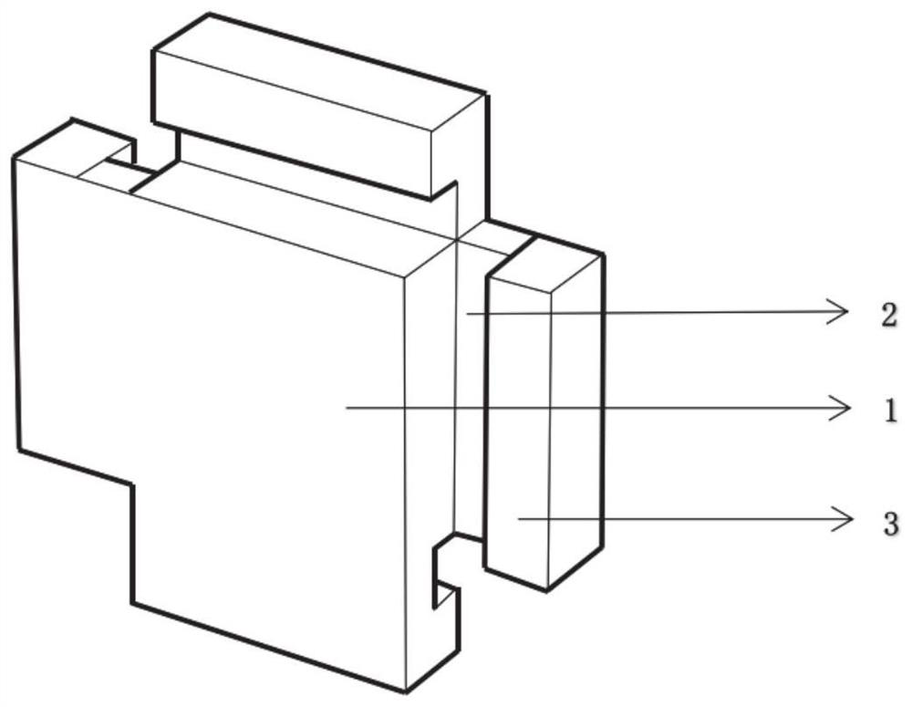
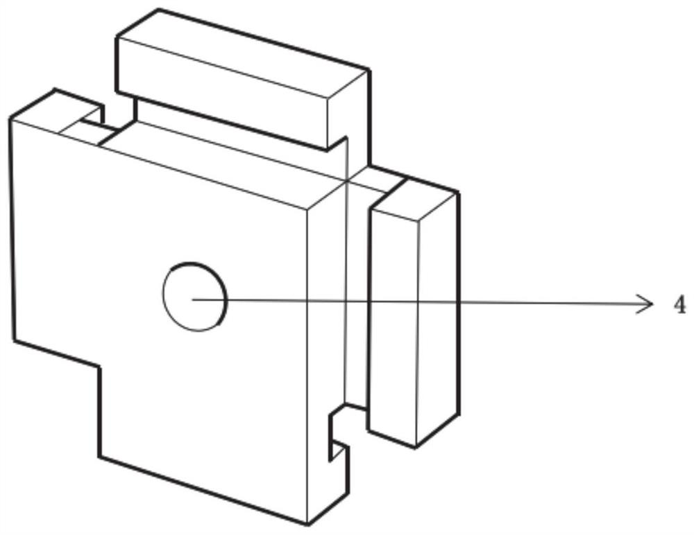
[0036] Such as figure 1 As shown, the retaining wall can be formed by splicing a plurality of retaining wall modules, the retaining wall module includes a module body 1, the four sides of the module body are provided with a splicing structure, and adjacent retaining wall modules can be connected through the splicing structure. splice connection.

[0037] The splicing structure adopts an L-shaped structure, including a first splicing part 2 and a se...


PUM


Abstract

The invention relates to a roadbed widening method. A roadbed widening structure formed by arranging foam light soil roadbed building blocks is constructed at one side of an original roadbed layer by layer, a retaining wall in contact with the outer side surface of the widening structure is constructed in the outer side of the widening structure after each layer of widening structure is constructed, the retaining wall is formed by splicing a plurality of retaining wall modules arranged in sequence, the widening structure is constructed layer by layer till the first set height is reached, and the retaining wall is constructed layer by layer till the second set height is reached. By means of the method, the stability of the roadbed can be guaranteed on the premise that the construction speed of the foam light soil roadbed building blocks is guaranteed.

Description

technical field [0001] The invention relates to the technical field of road engineering, in particular to a roadbed widening method. Background technique [0002] The statements herein merely provide background information related to the present invention and do not necessarily constitute prior art. [0003] Roadbed widening is a necessary link in the widening and reconstruction of highways at all levels. Using foam light soil to fill widened roadbeds is a new technology. At present, some scholars have proposed to use foam lightweight soil blocks for subgrade masonry, which can not only greatly increase the construction speed, but also have stable performance after foam lightweight soil masonry, and it is expected to have a better service state. However, the inventors have found that when the foam lightweight soil block subgrade is subjected to loads such as vehicle loads on the upper part, it will slide along the masonry surface, resulting in the problem of insufficient st...

Claims


Application Information

Patent Timeline
Patent Type & Authority Applications(China)
IPC IPC(8): E01C3/04E01C3/06E02D17/02E02D17/18E02D29/02E02D5/74
CPCE01C3/04E01C3/06E02D17/02E02D17/18E02D29/0266E02D5/74E02D2600/30E02D2600/40
Inventor 张宏博李振江姚义胜孙玉海张昕毅苏聚卿刘志鲲李帅王珺张冉宋晓莉吴建清宋修广
Owner SHANDONG UNIV
Why Eureka
Try Eureka