
Coal mine electromechanical equipment

A technology of electromechanical equipment and coal mines, applied in mining equipment, mining equipment, safety devices, etc., can solve problems such as slippery coal mine ground, endangering the safety of the equipment itself or surrounding personnel, and position deviation, so as to prolong the service life and avoid corrosion , Increase the effect of exercise time

Pending Publication Date: 2021-11-05
杨迎加
View PDF0 Cites 0 Cited by
  • Summary
  • Abstract
  • Description
  • Claims
  • Application Information

AI Technical Summary

Problems solved by technology

[0004] Aiming at the deficiencies of the prior art, the present invention provides a kind of coal mine electromechanical equipment, which solves the need for sprinkling water in the existing coal mine mining, thereby avoiding coal mine spontaneous combustion and ensuring construction safety, but a large amount of water will cause the coal mine ground to be slippery, and construction equipment will When in use, the position will shift due to its own vibration, which will endanger the safety of the equipment itself or the surrounding personnel.

Method used


Image

  • Coal mine electromechanical equipment
  • Coal mine electromechanical equipment
  • Coal mine electromechanical equipment

Examples


Embodiment 1

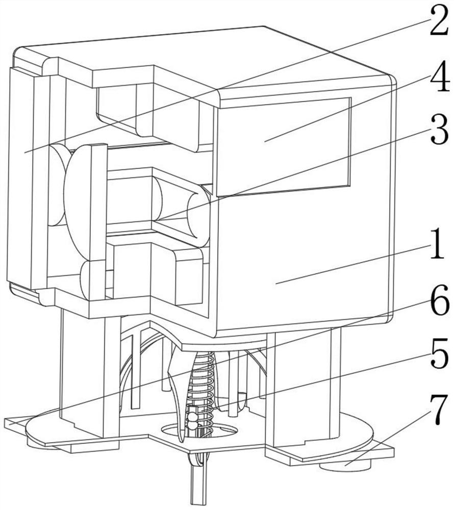
[0033] See figure 1 , 2 , 4, the present invention provides a technical solution: a coal mine mechanical and electrical equipment, including:

[0034] Equipment Box 1, the equipment box 1 has a casing, and a box door 2 mounted on the left side of the casing, and is disposed in the belt device 3 at the bottom of the casing, and the entrance and exit 4 of the front side of the box and the top of the back surface;

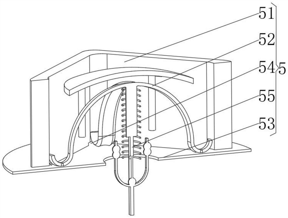
[0035] Moisture mechanism 5, the moisture-proof mechanism 5 is mounted at the bottom of the box, and the guide water plate 6 mounted at the bottom of the moisture-proof mechanism 5, and is fixed to the non-slip foot 7 at the bottom of the guide flow plate 6, and the coal mine is used by the guide water plate 6 The moisture of the ground dry evaporation is collected, avoiding the water generated in the drawing water plate 6 causes moisture to the coal mine floor, and after the dry evaporation of the moisture is collected, it will not cause environmental wet heat, effective...

Embodiment 2

[0042] See Figure 1-4 Based on the example one, the present invention provides a technical solution:

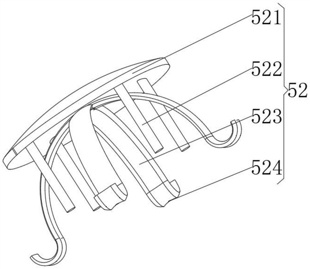
[0043] The flow guide 52 includes an arcuate top plate 521, as well as a guide post 522 mounted at the bottom of the curved top plate 521, and is disposed between the arcuate circuit plate 523 between the guide post 522, and is opened in an arcuate The through hole 524 of the top and bottom positions. Through the spherical surface design of the curved top plate 521, the motion impact generation generated by the equipment box 1 is uniformly dispersed, and the bottom member is protected to avoid damage to the bottom member, and the curved top plate 521 itself can be pair The evaporated moisture is conducted, drained to the fluid post 522 to achieve a condensed and flow of moisture.

[0044] The curved multi-fluid plate 523 is mounted at the corner of the moisture-proof box 51, and the through hole 524 penetrates the arc-shaped multifunctional plate 523 and extends to the top of the...

Embodiment 3

[0047] See figure 1 , 2 , 4, 5, on the basis of Examples One and Example 2, the present invention provides a technical solution: the sensing mechanism 555 includes a middle column A1, a magnetic ball A2 mounted at the bottom of the middle column A1, and mounted in magnet A2 The U-type vibrating bar A3 at the bottom of the outer surface is provided with a magnet A4 opposite to the magnetic pole of the magnetic ball A2 by the U-shaped rod A3 away from the magnetic ball A2. Using the vibration generated during operation, the U-shaped rod A3 is designed due to its own tuning, and the shock is formed, and the shift of the magnet A4 generates the position, forming a change in the magnetic field, and the electromagnetic sensor should cause the heating coil 551 to generate current, realize Energy auxiliary replenishment.

[0048] The middle column A1 is mounted at the top of the insulation ring 554, and the magnetic ball A2 and the U-shaped rod A3 are disposed in the insulation ring 554 l...


PUM


Abstract

The invention discloses coal mine electromechanical equipment. The coal mine electromechanical equipment specifically comprises an equipment box, a damp-proof mechanism, a flow guide water disc plate and anti-skid feet, wherein the equipment box is provided with a box body and a conveying belt device arranged at the bottom of an inner cavity of the box body; the damp-proof mechanism is arranged at the bottom of the box body, the flow guide water disc plate is arranged at the bottom of the damp-proof mechanism, and the anti-skid feet are fixed at the bottom of the flow guide water disc plate; and the damp-proof mechanism comprises a damp-proof box, the damp-proof box is provided with a square box body, a flow guide mechanism arranged on the inner surface of the square box body and an anti-backflow annular plate fixed at the bottom of the square box body. The invention relates to the technical field of coal mine electromechanics. According to the coal mine electromechanical equipment, a heating coil generated by the energy supply of the equipment is used for high-frequency heating, meanwhile, a heat conduction plate is used for transmitting heat to the ground, so that accumulated water on the ground is effectively dried, and water accumulation in a coal mine hole is avoided; and meanwhile, after the dried and evaporated water is collected, the damp and hot environment cannot be caused, the phenomenon of corrosion of the equipment is effectively avoided, and the service life is prolonged.

Description

Technical field [0001] The present invention relates to the field of coal miners, in particular a coal mine electromechanical equipment. Background technique [0002] Existing coal mines need to be sprinkled, avoid self-ignition of coal mines, ensuring construction safety, but a large number of water will lead to slippery coal mine fluffs, and the construction equipment will generate positional offset due to their own vibration, hazard equipment itself or surrounding personnel . Inventive content [0003] (1) Solving technical issues [0004] In response to the shortcomings of the prior art, the present invention provides a coal mine electromechanical equipment, which solves the existing coal mine mining needs to sprinkle water, thereby avoiding self-ignition of the coal mine, ensuring construction safety, but a large number of water will lead to slippery, construction equipment When using it, it will generate a positional offset, hazard the safety of the equipment itself or the...

Claims


Application Information

Patent Timeline
Patent Type & Authority Applications(China)
IPC IPC(8): E21F17/00E21F11/00
CPCE21F17/00E21F11/00
Inventor 杨迎加
Owner 杨迎加
Learn More