Method for replacing pre-embedded anchor bolt of concrete tower drum

A replacement method and pre-embedded anchor bolt technology, which is applied to the assembly of wind turbines, the configuration of installation/support of wind turbines, and wind power generation. Cost-effective, quick replacement effect

Pending Publication Date: 2021-11-05
SHANGHAI ELECTROMECHANICAL DESIGN & RES INST CO LTD
View PDF9 Cites 0 Cited by
  • Summary
  • Abstract
  • Description
  • Claims
  • Application Information

AI Technical Summary

Problems solved by technology

[0007] For fixed pre-embedded bolts, because the pre-embedded bolts are poured in the concrete tower, they cannot be disassembled, and only the entire concrete tube section can be replaced. stress, and then disassemble and replace the concrete tube section. After the concrete tube section is replaced, the steel strand is re-tensioned, and the steel tower, engine room, and impeller are installed. The whole process is time-consuming, labor-intensive, and costly
[0008] For the detachable pre-embedded bolts, the pre-embedded bolts are installed in the reserved holes of the concrete tube section through the anchor plate. Although the pre-embedded bolts can be taken out, the reserved holes for installing the pre-embedded bolts The randomness of the position is high, and the fracture position may be deep in the reserved hole, so the removal tool cannot be inserted into the reserved hole
At the same time, since the diameter of the pre-embedded holes is only slightly larger than that of the pre-embedded bolts (usually 3-5mm), there is no operating space for the rotation and disassembly of the pre-embedded bolts. Therefore, in actual operation, it is still difficult to remove the fracture in the concrete tower. The lower section of the embedded bolts in the interior affects the replacement of the embedded bolts

Method used


Image

  • Method for replacing pre-embedded anchor bolt of concrete tower drum
  • Method for replacing pre-embedded anchor bolt of concrete tower drum
  • Method for replacing pre-embedded anchor bolt of concrete tower drum

Examples


Embodiment 1

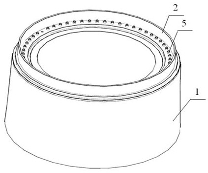
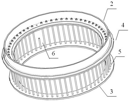
[0044] A certain pre-embedded bolt 5 in the concrete tube section 1 is broken. The diameter of the pre-embedded bolt 5 is 48 mm, and the diameter of the reserved hole for installing the pre-embedded bolt 5 is 52 mm. A technical bolt removal tool cannot take out the embedded bolt lower section 6.

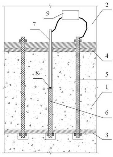
[0045] The concrete operation of adopting the present invention to remove the embedded bolt lower section 6 and install new embedded bolts 5 is as follows:

[0046]Step 1: After taking out the upper section of the broken embedded bolt, take a steel pipe with a diameter of 42mm, a wall thickness of 3mm, and a length of 1.2m as the conductive pipe 7, and insert the conductive pipe 7 into the reserved hole for installing the embedded bolt In this process, the lower end of the conductive pipe 7 is in contact with the top of the lower section 6 of the embedded bolt, and the upper end of the conductive pipe 7 extends to the top of the concrete cylinder section 1, and is located at about 30...


PUM


Abstract

The invention discloses a method for replacing a pre-embedded anchor bolt of a concrete tower drum. The method comprises the following steps of 1, taking out an upper section of the pre-embedded bolt, and inserting a conductive tube (7) into a preformed hole and contacting with the top of a lower section (6) of the pre-embedded bolt; 2, electroslag welding flux (8) is poured into the conductive tube; 3, connecting an electroslag welding machine (9), the conductive tube, the lower section of the pre-embedded bolt, a lower anchor plate (3) and the intact pre-embedded bolt (5) to form a current loop; 4, the electroslag welding machine is powered on to melt the electroslag welding flux, and the conductive tube is welded to the lower section of the pre-embedded bolt; 5, after the electroslag welding flux is cooled, the conductive tube and the lower section of the pre-embedded bolt are connected into a whole, and the conductive tube is rotated to drive the lower section of the pre-embedded bolt to be synchronously rotated and disassembled; and 6, taking out the conductive tube and the lower section of the pre-embedded bolt, and installing a new embedded bolt. According to the method, the lower section of the pre-embedded bolt fractured in the preformed hole of the concrete shell ring can be quickly taken out, so that the convenient replacement of the pre-embedded anchor bolt is realized.

Description

technical field [0001] The invention relates to a tower tube of a wind power generating set, in particular to a method for replacing pre-embedded anchor bolts in a concrete tower tube. Background technique [0002] As a clean energy technology, wind power has been widely used in the "Three North" regions with better wind resources in my country. With the development of the "Three Norths" region becoming increasingly saturated, wind power is developing in inland regions. Due to the low wind speed in inland areas and the increasing power of wind turbines, the diameter of the wind rotor is getting larger and the height of the tower is getting higher and higher. At present, the tower height of domestic onshore wind turbines has reached Reach 120-160m. The towers of wind power generators in the prior art include concrete towers, steel towers, and steel-concrete hybrid towers. [0003] In the steel-concrete hybrid tower, there are various connection methods between the steel to...

Claims


Application Information

Patent Timeline
Patent Type & Authority Applications(China)
IPC IPC(8): F03D13/20F03D13/10
CPCF03D13/20F03D13/10Y02E10/72Y02E10/728
Inventor 周瑞权钦明畅
Owner SHANGHAI ELECTROMECHANICAL DESIGN & RES INST CO LTD
Why Eureka
Try Eureka