Differential circuit, differential probe and oscilloscope assembly

A differential circuit and circuit technology, applied in the direction of instruments, measuring electrical variables, digital variables/waveform display, etc., can solve the problem of large output signal noise, reduce the impact and improve the accuracy

Active Publication Date: 2021-11-05
深圳麦科信科技有限公司
View PDF12 Cites 2 Cited by
  • Summary
  • Abstract
  • Description
  • Claims
  • Application Information

AI Technical Summary

Problems solved by technology

[0003] The main purpose of the present invention is to provide a differential circuit, aiming to solve the problem of excessive noise in the output signal of the existing differential probe when switching the attenuation ratio

Method used


Image

  • Differential circuit, differential probe and oscilloscope assembly
  • Differential circuit, differential probe and oscilloscope assembly
  • Differential circuit, differential probe and oscilloscope assembly

Examples


Embodiment Construction

[0035] The technical solutions in the embodiments of the present invention will be clearly and completely described below with reference to the accompanying drawings in the embodiments of the present invention. Obviously, the described embodiments are only a part of the embodiments of the present invention, not all of the embodiments. Based on the embodiments of the present invention, all other embodiments obtained by those of ordinary skill in the art without creative efforts shall fall within the protection scope of the present invention.

[0036] In addition, descriptions such as "first", "second", etc. in the present invention are only for descriptive purposes, and should not be construed as indicating or implying their relative importance or implicitly indicating the number of indicated technical features. Thus, a feature delimited with "first", "second" may expressly or implicitly include at least one of that feature. In addition, the technical solutions between the vari...


PUM


Abstract

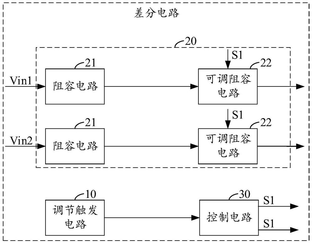
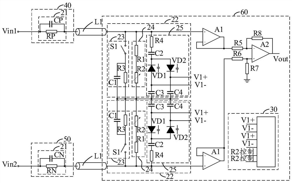
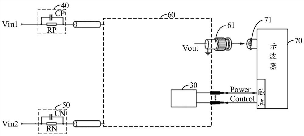
The invention discloses a differential circuit, a differential probe and an oscilloscope assembly. The differential circuit comprises an adjustment trigger circuit which is used for outputting an attenuation adjustment signal when being triggered, two attenuation circuits and a control circuit, wherein each attenuation circuit comprises a resistance-capacitance circuit and an adjustable resistance-capacitance circuit, an input end of the resistance-capacitance circuit is an input end of the attenuation circuit, an output end of the resistance-capacitance circuit is connected with an output end of the adjustable resistance-capacitance circuit in the attenuation circuit, and an output end of the adjustable resistance-capacitance circuit is an output end of the attenuation circuit; one resistance-capacitance circuit is used for accessing a first input signal, and the other resistance-capacitance circuit is used for accessing a second input signal; and the control circuit is used for adjusting resistance-capacitance values of the two adjustable resistance-capacitance circuits according to the attenuation adjustment signal outputted by the adjustment output circuit, so the two attenuation circuits attenuate the first input signal and the second input signal by a first preset proportion and then output the first input signal and the second input signal. According to the differential circuit, when a attenuation ratio is switched, the noise in the output signal is not too large.

Description

technical field [0001] The invention relates to the technical field of differential probes, in particular to a differential circuit, a differential probe and an oscilloscope assembly. Background technique [0002] Currently, differential probes are commonly used to measure high-voltage signals. The existing traditional high-voltage differential probe will be provided with a switch for switching the differential probe voltage divider ratio gear, also known as the attenuation ratio gear, but in fact, the switch changes the differential by changing the gain of the back-end circuit in the differential probe. The attenuation ratio of the probe as a whole. In this way, when switching to a gear with a smaller attenuation ratio, the noise of the back-end circuit will be amplified synchronously, so that the influence of the noise on the output signal of the differential probe will also be amplified synchronously. SUMMARY OF THE INVENTION [0003] The main purpose of the present i...

Claims


Application Information

Patent Timeline
Patent Type & Authority Applications(China)
IPC IPC(8): G01R13/00
CPCG01R13/00
Inventor 张兴杰
Owner 深圳麦科信科技有限公司
Why Eureka
Try Eureka