
Outdoor low-voltage power distribution cabinet

A power distribution cabinet and low-voltage technology, which is applied in the field of outdoor low-voltage power distribution cabinets, can solve the problems of dust-proof net blockage, adhesion, and the inability of low-voltage power distribution cabinets to effectively dissipate heat, so as to improve heat dissipation performance and improve service life. Effect

Inactive Publication Date: 2021-11-05
陆强胜
View PDF0 Cites 3 Cited by
  • Summary
  • Abstract
  • Description
  • Claims
  • Application Information

AI Technical Summary

Problems solved by technology

[0003] The existing low-voltage power distribution cabinets for outdoor use have cooling holes on the outer surface of the chassis in order to meet the heat dissipation requirements, and the dust in the air will enter the chassis through the cooling holes, affecting the normal use of the device. The cabinet will install dust-proof nets at the cooling holes to prevent dust from entering the low-voltage power distribution cabinet. However, in areas with a lot of wind and sand, a small amount of dust will still enter the low-voltage power distribution cabinet through the dust-proof net And after the dust-proof net is used for a long time, dust will adhere to the dust-proof net, resulting in the blockage of the dust-proof net, which will cause the problem that the low-voltage power distribution cabinet cannot effectively dissipate heat. Therefore, we propose a low-voltage power distribution cabinet for outdoor use. cabinet

Method used


Image

  • Outdoor low-voltage power distribution cabinet
  • Outdoor low-voltage power distribution cabinet
  • Outdoor low-voltage power distribution cabinet

Examples


Embodiment Construction

[0025] The following will clearly and completely describe the technical solutions in the embodiments of the present invention with reference to the accompanying drawings in the embodiments of the present invention. Obviously, the described embodiments are only some, not all, embodiments of the present invention.

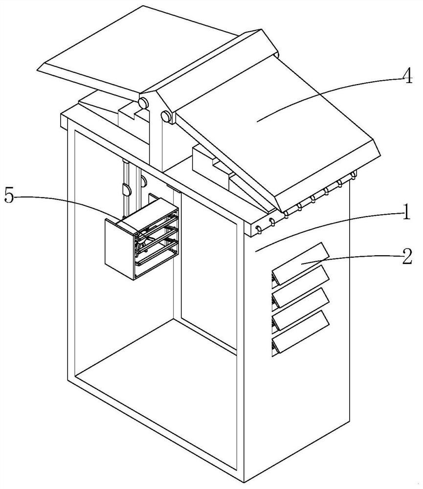
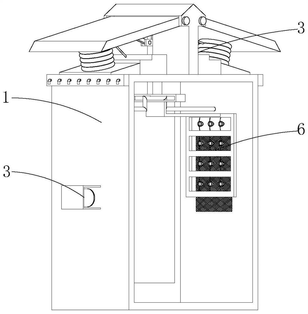
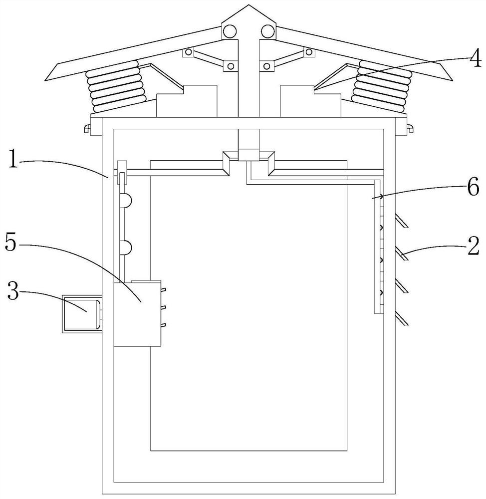
[0026] see Figure 1-7 , the present invention provides a technical solution: an outdoor low-voltage power distribution cabinet, including a power distribution cabinet main body 1, a rainproof plate 2 and a motor 3, a motor 3 is fixed on the left side of the power distribution cabinet main body 1, and the motor 3 The output shaft extends to the inside of the main body 1 of the power distribution cabinet, and the rainproof plate 2 is embedded on the right side of the main body 1 of the power distribution cabinet. The inner left side of the electric cabinet main body 1 is provided with a heat dissipation mechanism 5 for dissipating heat from the electrical components i...


PUM


Abstract

The invention discloses an outdoor low-voltage power distribution cabinet, and relates to the technical field of low-voltage power distribution cabinets. The outdoor low-voltage power distribution cabinet comprises a power distribution cabinet main body, a rainproof plate and a motor, the top of the power distribution cabinet main body is fixedly provided with a dust falling mechanism used for carrying out dust falling treatment on dust, and the left side of the interior of the power distribution cabinet main body is provided with a heat dissipation mechanism used for carrying out heat dissipation on electrical elements in the power distribution cabinet main body; and a cleaning mechanism for cleaning a dustproof net is arranged on the right side in the power distribution cabinet main body. According to the outdoor low-voltage power distribution cabinet, the protruding part of a rotating rod is matched with a sliding groove plate, so that the sliding groove plate drives a push rod to move up and down; under the action of a hinge rod, a pressing plate overturns downwards to extrude a liquid bag, water in the liquid bag is sprayed out of mist through an atomizing nozzle, and therefore the situation that dust easily enters the power distribution cabinet main body in areas where the amount of wind, sand and dust is large is avoided, the situation that the normal use of internal electric components in the power distribution cabinet main body are affected by the dust can be avoided, and the service life of the power distribution cabinet main body is prolonged.

Description

technical field [0001] The invention relates to the technical field of low-voltage power distribution cabinets, in particular to an outdoor low-voltage power distribution cabinet. Background technique [0002] The rated current of the low-voltage power distribution cabinet is AC 50Hz, and the power distribution system with a rated voltage of 380v is used for power conversion and control of power, lighting and power distribution. The product has the characteristics of strong breaking capacity, good dynamic and thermal stability, flexible electrical scheme, convenient combination, series, strong practicability, and novel structure. [0003] The existing low-voltage power distribution cabinets for outdoor use have cooling holes on the outer surface of the chassis in order to meet the heat dissipation requirements, and the dust in the air will enter the chassis through the cooling holes, affecting the normal use of the device. The cabinet will install dust-proof nets at the coo...

Claims


Application Information

Patent Timeline
IPC IPC(8): H02B1/28H02B1/56H02B1/36H02B1/30H02B1/32B01D46/00B01D46/10
CPCH02B1/28H02B1/565H02B1/36H02B1/30H02B1/32B01D46/10B01D46/0053
Inventor 陆强胜
Owner 陆强胜
Learn More