Hardware bending machine

A bending machine and hardware technology, applied in the field of hardware, can solve the problems of different bending machines, danger, and workpieces leaving the machine, etc., to achieve the effects of optimizing bending effect, improving functionality, and improving safety

Pending Publication Date: 2021-11-09
邹道军
View PDF0 Cites 0 Cited by
  • Summary
  • Abstract
  • Description
  • Claims
  • Application Information

AI Technical Summary

Problems solved by technology

[0004] In view of the deficiencies in the prior art, the present invention provides a bending machine for hardware, which solves the problem that the bending machine cannot perform different bending forces according to different hardware, which may cause different bending degrees of the hardware, and Pipe-type hardware cannot be accurately fixed to the bending table, which may cause the workpiece to fall out of the machine during processing, causing dangerous problems

Method used


Image

  • Hardware bending machine
  • Hardware bending machine
  • Hardware bending machine

Examples


Embodiment 1

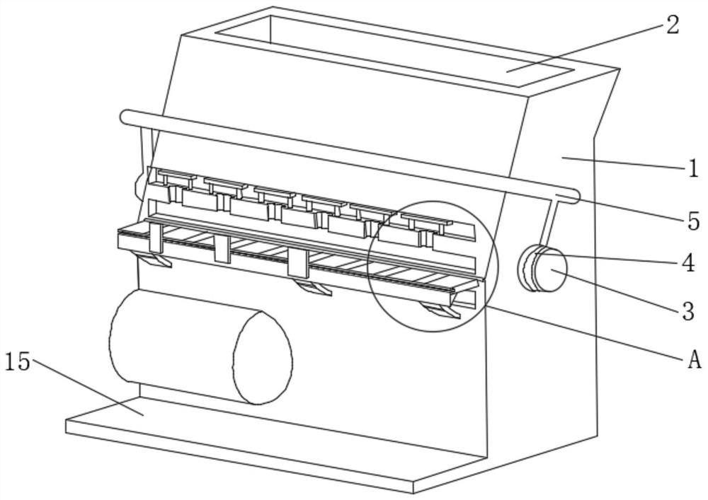
[0034] see Figure 1-2 , the present invention provides a technical solution: a bending machine for hardware, including a chassis 1, the top of the chassis 1 is provided with a heat dissipation window 2, the left and right sides of the outer surface of the chassis 1 are fixedly connected with a fixed plate 3, the fixed plate The outer surface of 3 is provided with a strip groove 4, and two strip grooves 4 are provided with two. The inner surfaces of the two strip grooves 4 are fixedly connected with fixing rods, and the opposite sides of the two fixing rods are fixedly connected with a safety rod. Bar 5, the outer surface of safety bar 5 is covered with rubber sleeve, the outer surface of chassis 1 is provided with transverse groove 6 successively from top to bottom, and there are three transverse grooves 6, and the inner surface of upper transverse groove 6 is evenly fixedly connected with a stable Mechanism 7, the bottom of the upper horizontal groove 6 is uniformly provided...

Embodiment 2

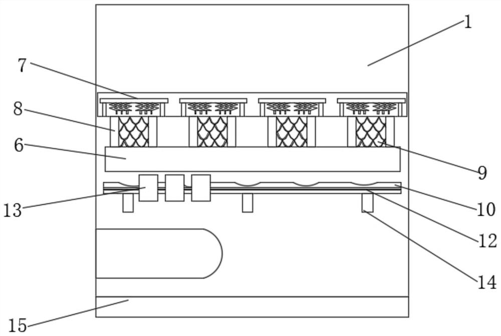
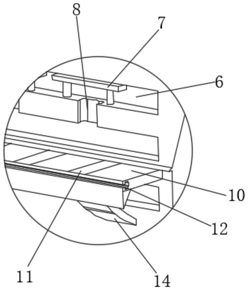
[0036] see Figure 1-3 , the present invention provides a technical solution: the stabilizing mechanism 7 includes a vertical rod 71, the bottom of the vertical rod 71 is fixedly connected with the bottom of the inner surface of the upper horizontal groove 6, and the tops of the two vertical rods 71 ​​are fixedly connected with a baffle 72, the baffle Both left and right sides of the bottom of the 72 are fixedly connected with a telescopic platform 73, and the bottom of the telescopic platform 73 is evenly and fixedly connected with a limiting column 74. Prevent the workpiece from detaching from the outer surface of the work plate 10 and the upward movement of the workpiece may cause extrusion to the transverse groove 6. When the workpiece is upwardly extruded, by contacting the telescopic table 73, the distance of the upward movement of the hardware workpiece is controlled. Excessive death causes the hardware to bend.

Embodiment 3

[0038] see Figure 2-7 , the present invention provides a technical solution: the anti-skid mechanism 9 includes a conical bottom block 91 connected, the bottom of the conical bottom block 91 is fixedly connected with the inner wall of the special-shaped groove 8, and the outer surface of the conical bottom block 91 is rotatably connected with an upper cover plate 92 , a connection mechanism 93 is provided between the bottom of the upper cover plate 92 and the bottom of the conical bottom block 91 . The internal space of the special-shaped groove 8 is reduced, thereby preventing the workpiece from continuing to move upward, and controlling the workpiece to produce a large displacement action.

[0039] The connection mechanism 93 includes a connection belt, and the left and right ends of the connection belt are respectively fixedly connected to the inner surface of the upper cover plate 92 and the inner surface of the conical bottom block 91 .

[0040] The bottom of the upper ...


PUM


Abstract

The invention discloses a hardware bending machine, and relates to the technical field of hardware. The invention discloses a hardware bending machine. The hardware bending machine comprises a machine box, a heat dissipation window is formed in the top of the machine box, fixing discs are fixedly connected to the left side and the right side of the outer surface of the machine box correspondingly, two strip-shaped grooves are formed in the outer surface of each fixing disc, fixing rods are fixedly connected to the inner surfaces of the two strip-shaped grooves correspondingly, and a safety rod is fixedly connected between the opposite sides of the two fixing rods. A stabilizing mechanism and an anti-skid mechanism are additionally arranged in the machine box, when a hollow hardware workpiece is bent, due to the fact that the hardware is prone to displacement in the bending process, the bending effect is poor due to the fact that extrusion force is inconsistent, the workpiece can be prevented from excessively displacing through the anti-skid mechanism when the hardware moves upwards, meanwhile, the stabilizing mechanism prevents the workpiece from being directly punched upwards to scratch the exterior of the case, the functionality of the bending machine is improved, and the bending effect of the machine on hardware is optimized at the same time.

Description

technical field [0001] The invention relates to the technical field of hardware, in particular to a bending machine for hardware. Background technique [0002] Hardware, traditional hardware products, also known as "hardware". Refers to the five metals of gold, silver, copper, iron, and tin. After manual processing, it can be made into works of art or metal devices such as knives and swords. Hardware in modern society is more extensive, such as hardware tools, hardware parts, daily hardware, construction hardware and security supplies. [0003] Most of the existing bending machines are used for crimping and other work on the board surface. When targeting some types of pipes or hollow hardware, different bending forces cannot be applied according to different hardware, which may cause hardware damage. The degree of bending is different, and the hardware of the pipe type cannot be accurately fixed with the bending processing table, which may cause the workpiece to leave the...

Claims


Application Information

Patent Timeline
IPC IPC(8): B21D43/00B21D7/00B21D55/00
CPCB21D43/003B21D7/00B21D55/00
Inventor 邹道军
Owner 邹道军
Why Eureka
Try Eureka