
A nozzle for liquid beam electroforming of square-section metal structures

A metal structure and nozzle technology, applied in electroforming, electrolysis process, etc., can solve the problems of high liquid beam center, reduced surface area, strong impact of cathode substrate, etc., to achieve small liquid resistance, reduce surface tension effect and liquid resistance , the effect of small surface tension

Active Publication Date: 2022-07-26
HENAN POLYTECHNIC UNIV +1
View PDF7 Cites 0 Cited by
  • Summary
  • Abstract
  • Description
  • Claims
  • Application Information

AI Technical Summary

Problems solved by technology

[0003] At present, the nozzles used in liquid beam electroforming are generally circular nozzles. Although this type of nozzle can produce circular cross-section cylindrical metal parts with good structural symmetry, due to the effect of surface tension around the electroforming liquid beam, it The flow velocity of the formed liquid jet often presents an uneven distribution feature with a high center and a low periphery.
Moreover, if it is necessary to manufacture a metal product with a width much larger than the diameter of the circular nozzle, it must be realized by repeated shifting and scanning. Even so, the cross-sectional shape of the metal part is difficult to appear square features, and this shift scanning method inevitably leads to the occurrence of electroformed layer overlap or seam defects
In this regard, if the direct use of square mouth nozzles (especially large aspect ratio square mouth nozzles) should bring certain positive effects, however, it is extremely difficult for conventional square mouth nozzles to meet the ideal preparation requirements
This is because, if Figure 4 As shown, when the electroforming liquid flow with a relatively low flow rate leaves the square-mouth nozzle and enters the machining gap to form an electroforming liquid beam, the liquid beam is no longer restricted by the surface tension and shaping effect of the inner wall of the nozzle and is in a relatively free state. , at this time, due to the surface tension at the gas-liquid interface and the surface area minimization effect, the liquid beam gradually deforms after a small distance away from the square-mouth nozzle, and the original surface tension of the inner wall of the long side of the square-mouth nozzle is greater The acting liquid jet becomes shorter and rounder to reduce its surface area, and then becomes an elliptical cross-section liquid jet, and then further becomes a circular cross-section liquid jet. In this way, the square mouth nozzle finally loses its ability to form a square cross-section liquid jet Therefore, based on the conventional square mouth nozzle, the expected square cross-section metal structure cannot be electroformed by the liquid beam.
[0004] Although the flow rate of electroforming liquid is extremely high and the processing gap is smaller, the electroforming liquid beam leaving the square mouth nozzle can maintain a square cross-sectional feature for a long distance to the surface of the cathode substrate, but such a liquid beam impacts on the cathode substrate. Powerful, the distribution of the flow field is extremely uneven, and the reflection of the liquid flow is serious, it is not suitable as a tool carrier for electroforming, and it is impossible to electroform a high-quality square-section metal structure based on this
There is also a method of mask electroforming (such as the technical solution described in the patent application number CN201810822448.X) that first uses a high-cost photolithography process to prepare a square film structure, and then performs electrodeposition replication, but this method relies heavily on The photolithography film-making process with complex operation steps, and it is impossible to prepare three-dimensional complex shape parts with free spatial changes

Method used


Image

  • A nozzle for liquid beam electroforming of square-section metal structures
  • A nozzle for liquid beam electroforming of square-section metal structures
  • A nozzle for liquid beam electroforming of square-section metal structures

Examples


Embodiment Construction

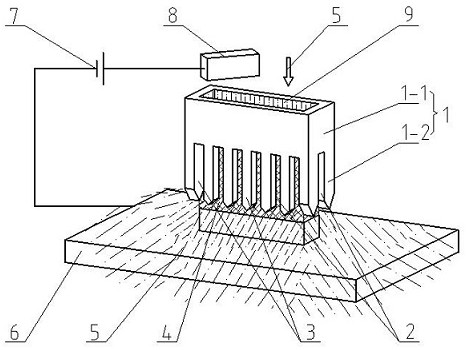
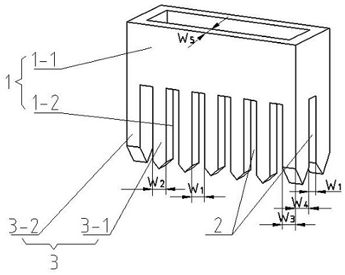
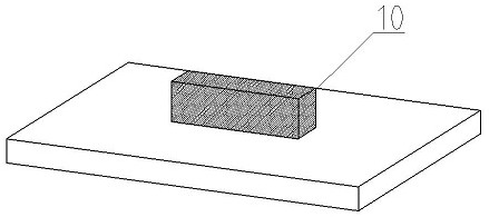
[0020] Combine below figure 1 , figure 2 , image 3 The specific implementation process of "a nozzle for liquid beam electroforming square-section metal structure" of the present invention is described in detail.

[0021] A nozzle for liquid beam electroforming of square-section metal structures according to the present invention, such as figure 2 As shown, the nozzle 1 is in the shape of a hollow square tube with a rectangular cross-section of equal wall thickness. The length of the long side of the rectangular nozzle 1 is 2.08mm, the length of the short side is 0.8mm, and the wall thickness w 5 It is 160 μm, and is provided with an upper guide section 1-1 and a lower guide section 1-2 with microgrid slits 2 and microgrids 3 around it. The microgrids 3 include 10 central microgrids 3 - 1 located in the middle of the two long sides of the nozzle 1 and 4 corner microgrids 3 - 2 located at the two corners of the two short sides of the nozzle 1 . The height of the upper gu...


PUM

PropertyMeasurementUnit
widthaaaaaaaaaa
heightaaaaaaaaaa

Abstract

The invention discloses a nozzle for liquid beam electroforming of a square-section metal structure. The nozzle is in the shape of a hollow square tube with a rectangular cross-section of equal wall thickness and is provided with an upper guide section and a nozzle with micro-grid slits and micro-grids around it. In the lower guide section, the microgrids include a central microgrid located at the middle of each side of the nozzle and corner microgrids located at the four corner edges. The width w of the microgrid slit 1 and the width w of the middle microgrid 2 equal. Thickness w of corner grid 3 Equal to the wall thickness w of the nozzle 5 , width w 4 equal to w 5 with w 2 Sum. The side of the lower end of the micro grid is provided with a 45° chamfer. Due to the setting of the micro grid slit, the contact area between the electroforming liquid flow and the inner wall of the nozzle can be greatly reduced, so that the liquid flow can bear a smaller surface tension before entering the processing gap to form a liquid beam, and the liquid resistance is also reduced accordingly, which is beneficial to The shrinkage and deformation of the liquid beam are slowed down and the shape of the square cross-section is maintained, thereby electroforming a metal structure with a square cross-section. The purpose of the present invention is to provide a nozzle that can efficiently form a high-precision square-section metal structure at one time by means of liquid beam electroforming.

Description

technical field [0001] The invention relates to a nozzle for liquid beam electroforming of a square-section metal structure, belonging to the technical field of electrodeposition processing. Background technique [0002] Electroforming is a special processing technology based on the principle of electrochemical deposition to achieve precise features and parts manufacturing. Jet electroforming is one of the most representative electroforming technologies. It has great development potential in the field of metal additive manufacturing due to its advantages of good localization and high degree of freedom of operation. Liquid beam electroforming (Wang Wei, Ming Pingmei, etc.. Research on micro-liquid column confined electrodeposition processing technology [A]. Proceedings of the 18th National Conference on Special Machining (Abstract) [C]. Chinese Mechanical Engineering Society Special Machining Chapter, 2019: 1.) is a special form of jet electroforming. This technology uses a...

Claims


Application Information

Patent Timeline
Patent Type & Authority Patents(China)
IPC IPC(8): C25D1/00
CPCC25D1/00
Inventor 明平美张亚楠周涛李真明牛屾闫亮李欣潮王伟曹军崔成强
Owner HENAN POLYTECHNIC UNIV
Learn More