Pile foundation reinforcement cage position control device and installation method

A technology of a pile foundation reinforcement cage and a control device, which is applied to sheet pile walls, infrastructure engineering, construction, etc., can solve problems such as inability to effectively fix reinforcement cage reinforcement cages and inconvenience in hoisting reinforcement cages.

Inactive Publication Date: 2021-11-09
CHINA MCC17 GRP
View PDF2 Cites 0 Cited by
  • Summary
  • Abstract
  • Description
  • Claims
  • Application Information

AI Technical Summary

Problems solved by technology

[0004] The technical problem to be solved by the present invention is: it is impossible to effectively fix the reinforcement cage and limit the floating problem of the reinforcement cage during pouring, and the hoisting of the reinforcement cage is inconvenient

Method used


Image

  • Pile foundation reinforcement cage position control device and installation method
  • Pile foundation reinforcement cage position control device and installation method
  • Pile foundation reinforcement cage position control device and installation method

Examples


Embodiment 1

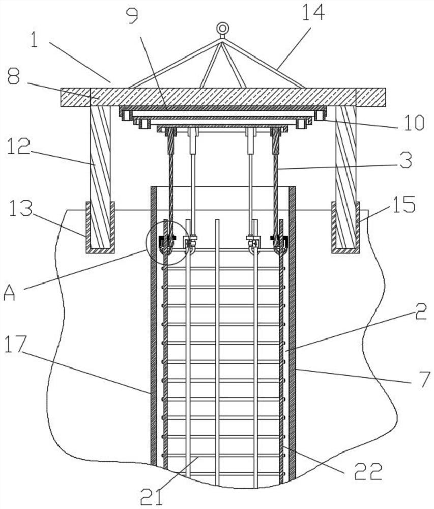
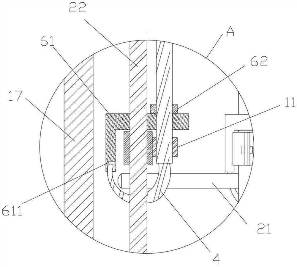
[0034] like Figure 1 to Figure 4 As shown, it is an embodiment of the present invention, a pile foundation reinforcement cage position control device, including a positioning frame 1 and a reinforcement cage 2, the positioning frame 1 is installed with a connector 3, and the connector 3 is provided with at least four groups, The upper ends of the multiple sets of connectors 3 are welded with the positioning frame 1, and the bottom ends of the connectors 3 are installed with a bearing portion 4, a connecting portion 5 and a limiting portion 6, and the bearing portion 4 is suitable for supporting the stirrups 21 of the reinforcement cage 2, connecting The part 5 is suitable for connecting to the main rib 22 of the reinforcement cage 2, the connecting part 5 is installed between the bearing part 4 and the limiting part 6, the connecting part 5 is movably connected on the connecting part 3, and the limiting part 6 is installed on the connecting part 5 At the upper end of the cage...

Embodiment 2

[0050] like Figure 5 As shown, it is another embodiment of the present invention. On the basis of Example 1, the bearing part 4 includes a circular plate, which is fixedly connected with the connecting piece 3, and the circular plate is suitable for supporting the stirrup 21, and the limit plate 61 Including the arc side, the circular plate is provided with a socket groove 41, the arc side is adapted to the socket groove 41, and the limit plate 61 is suitable for snapping downward in the socket groove 41, and the socket groove 41 and the limit The closing of the bit plate 61 strengthens the actual locking effect.


PUM


Abstract

The invention discloses a pile foundation reinforcement cage position control device and an installation method, and belongs to the field of reinforcement cage positioning. The pile foundation reinforcement cage position control device comprises a positioning frame and a reinforcement cage; multiple sets of connecting pieces are installed in the positioning frame; the upper ends of the multiple sets of connecting pieces are connected with the positioning frame; a bearing part, a connecting part and a limiting part are installed at the bottom end of each connecting piece; the bearing parts are suitable for supporting stirrups of the reinforcement cage; the connecting parts are suitable for being connected to a main reinforcement of the reinforcement cage; the connecting parts are installed between the bearing parts and the limiting parts; the connecting parts are movably connected to the connecting pieces; the limiting parts are installed at the upper ends of the connecting parts; the limiting parts are suitable for limiting the positions of the stirrups of the reinforcement cage; a pile foundation hole is formed in the lower portion of the positioning frame; and the reinforcement cage is installed in the pile foundation hole. The technical problems that the reinforcement cage cannot be effectively fixed and cannot be limited to float upwards during pouring, and hoisting of the reinforcement cage is inconvenient are solved.

Description

technical field [0001] The invention belongs to the field of reinforcement cage positioning, and in particular relates to a position control device and an installation method of a pile foundation reinforcement cage. Background technique [0002] As a commonly used substructure form in engineering construction, bored piles are widely used. The hoisting of the pile foundation reinforcement cage will directly affect the quality of the pile foundation and the supporting effect of the pile foundation design. [0003] In the construction of the project, it is stipulated that the steel frame should not be directly supported at the bottom of the hole, but should be hung at the designated position in the design. The conventional hanging method is to use wire rope to hang it on the steel casing of the hole. The steel wire rope is easily deformed, causing the reinforcement cage to sink. During the concrete pouring process, the extubation and the buoyancy of the concrete pouring will ca...

Claims


Application Information

Patent Timeline
Patent Type & Authority Applications(China)
IPC IPC(8): E02D5/34E02D27/12
CPCE02D5/34E02D27/12
Inventor 夏云云朱金坤吴雪萍王进源
Owner CHINA MCC17 GRP
Why Eureka
Try Eureka