
Wear-resistant inlay, valve plate, guide rail, valve plate assembly and slide valve

A valve plate and inlay technology, applied in the direction of sliding valves, valve details, valve devices, etc., can solve the problems of valve plate, guide rail damage, complex media, harsh working environment, etc., to achieve convenient connection and improve local wear resistance Effect

Pending Publication Date: 2021-11-09
洛阳超蓝节能技术有限公司 +1
View PDF0 Cites 0 Cited by
  • Summary
  • Abstract
  • Description
  • Claims
  • Application Information

AI Technical Summary

Problems solved by technology

Due to the special use location, complex media passing through it, and harsh working environment, the main components inside the catalytic cracking slide valve, such as valve plates and guide rails, are easily damaged, often causing safety hazards to the stable operation of the device
[0003] In order to increase the wear resistance of valve plates, guide rails and other components, the traditional method is to surfacing hard alloy wear-resistant linings on the parts that are prone to wear, but this method has limited improvement in wear resistance and high cost. Easy to fall off

Method used


Image

  • Wear-resistant inlay, valve plate, guide rail, valve plate assembly and slide valve
  • Wear-resistant inlay, valve plate, guide rail, valve plate assembly and slide valve
  • Wear-resistant inlay, valve plate, guide rail, valve plate assembly and slide valve

Examples


Embodiment Construction

[0073] The present application will be further described in detail below. It should be understood that the specific embodiments described here are only used to explain related inventions, rather than to limit the invention. It should be noted that, in the case of no conflict, the embodiments in the present application and the features in the embodiments can be combined with each other.

[0074] The present invention is an improvement to the slide valve, specifically, an improvement to the guide rail and valve plate assembly, the guide rail and / or the valve plate of the slide valve. Body realized.

[0075] Various embodiments of the wear-resistant inlay, the valve plate, the guide rail, the guide rail and valve plate assembly, and the slide valve will be described in detail below with reference to the accompanying drawings.

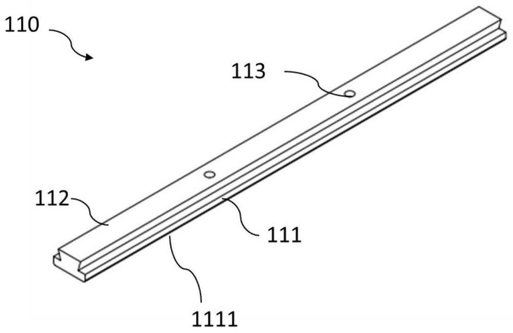
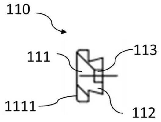
[0076] figure 1 is a perspective view of a first embodiment of a wear-resistant inlay according to the invention; figure 2 yes figure 1 Front view o...


PUM


Abstract

The invention discloses a wear-resistant inlay used for a valve plate or a guide rail of a slide valve. The wear-resistant inlay comprises a sliding part and an assembling part, wherein the sliding part comprises a long and thin extending main body, the long and thin extending main body comprises a sliding surface used as a sliding surface of the valve plate or the guide rail, and the assembling part extends out from the side, opposite to the sliding surface, of the sliding part and is used for assembling the wear-resistant inlay to the valve plate or the guide rail. The invention further discloses the valve plate, the guide rail, a valve plate assembly and the slide valve, wherein the valve plate, the guide rail, the valve plate assembly and the slide valve comprise the wear-resistant inlay. The wear-resistant inlay is locally applied to the valve plate or the guide rail of the slide valve through the assembling part structure of the wear-resistant inlay, the wear-resistant inlay can be conveniently connected with the valve plate or the guide rail of the slide valve, the local wear resistance of the valve plate or the guide rail of the slide valve can be effectively improved, meanwhile, the strength of the valve plate or the guide rail cannot be reduced, and therefore the performance of the valve plate, the performance of the guide rail and the performance of the slide valve are improved.

Description

technical field [0001] The invention relates to the field of petrochemical industry, in particular to a wear-resistant inlay for a slide valve used in catalytic cracking. The invention also relates to a valve plate, a guide rail, a guide rail and valve plate assembly and a slide valve comprising the wear-resistant inlay. Background technique [0002] The catalytic cracking slide valve is mainly used in the catalyst circulation pipeline or flue gas pipeline, and the medium passing through it is high-temperature catalyst or high-temperature flue gas with catalyst particles. Due to the special use location, complex media passing through it, and harsh working environment, the main components inside the catalytic cracking slide valve, such as the valve plate and guide rail, are easily damaged, which often poses a safety hazard to the stable operation of the device. [0003] In order to increase the wear resistance of valve plates, guide rails and other components, the traditiona...

Claims


Application Information

Patent Timeline
IPC IPC(8): F16K3/02F16K3/314F16K3/316F16K27/04
CPCF16K3/02F16K3/314F16K3/316F16K27/044
Inventor 程向锋武立国杨芳
Owner 洛阳超蓝节能技术有限公司
Learn More