
A polarity detection device for a current transformer

A current transformer and polarity detection technology, applied in the field of transformer detection, can solve problems such as unreliable testing, high operational risk, and inability to accurately verify the threshold value

Active Publication Date: 2022-03-22
HUIZHOU POWER SUPPLY BUREAU OF GUANGDONG POWER GRID CO LTD +1
View PDF9 Cites 0 Cited by
  • Summary
  • Abstract
  • Description
  • Claims
  • Application Information

AI Technical Summary

Problems solved by technology

[0003] At present, for the rapid detection method and instrument of current transformer polarity, the DC pointer method is generally used to directly connect the 220V AC mains power to the DC system. There is a risk of personal electric shock when connected to the mains power supply; second, the test is unreliable-manually connected to the mains, and the temporary wiring is unreliable; third, the test result is inaccurate-the threshold value of AC jumping is 10V, which is different from the 220V applied With a large deviation, the threshold value cannot be accurately verified

Method used

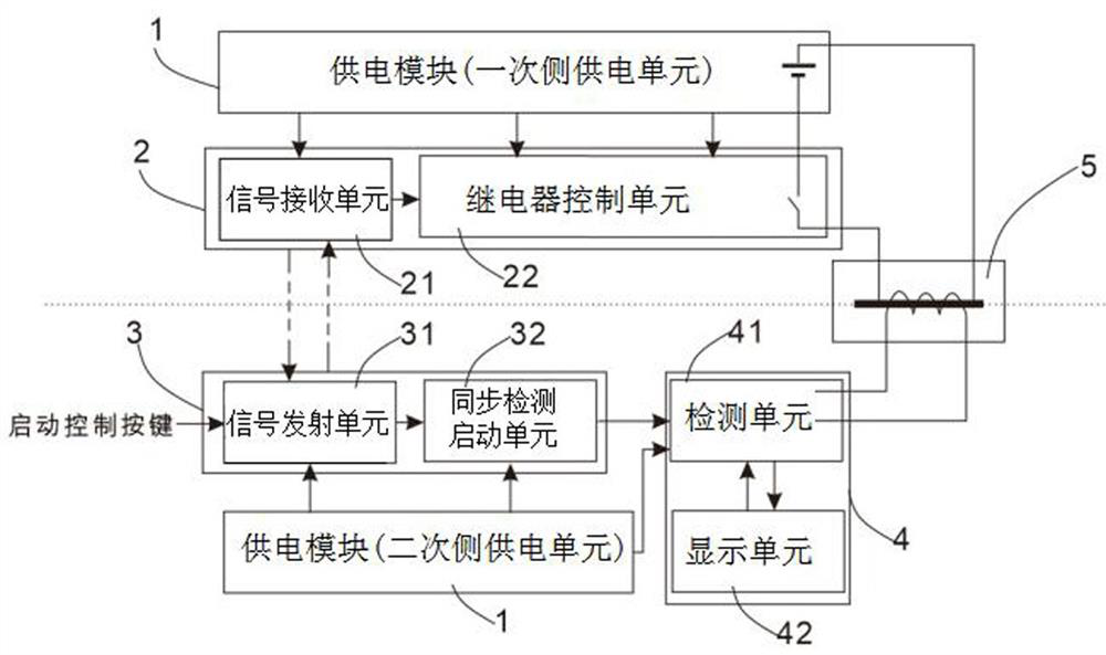

Image

  • A polarity detection device for a current transformer
  • A polarity detection device for a current transformer
  • A polarity detection device for a current transformer

Examples


Embodiment Construction

[0025] In order to make the object, technical solution and advantages of the present invention more clear, the present invention will be further described in detail below in conjunction with the accompanying drawings and embodiments. It should be understood that the specific embodiments described here are only used to explain the present invention, not to limit the present invention.

[0026] It should be noted that, when an element is referred to as being “mounted on”, “fixed on” or “disposed on” another element, it may be directly on the other element or there may be an intervening element at the same time. When an element is referred to as being "connected to" another element, it can be directly connected to the other element or intervening elements may also be present.

[0027] It should also be noted that the orientation terms such as left, right, up, and down in the embodiments of the present invention are only relative concepts or refer to the normal use state of the pr...


PUM


Abstract

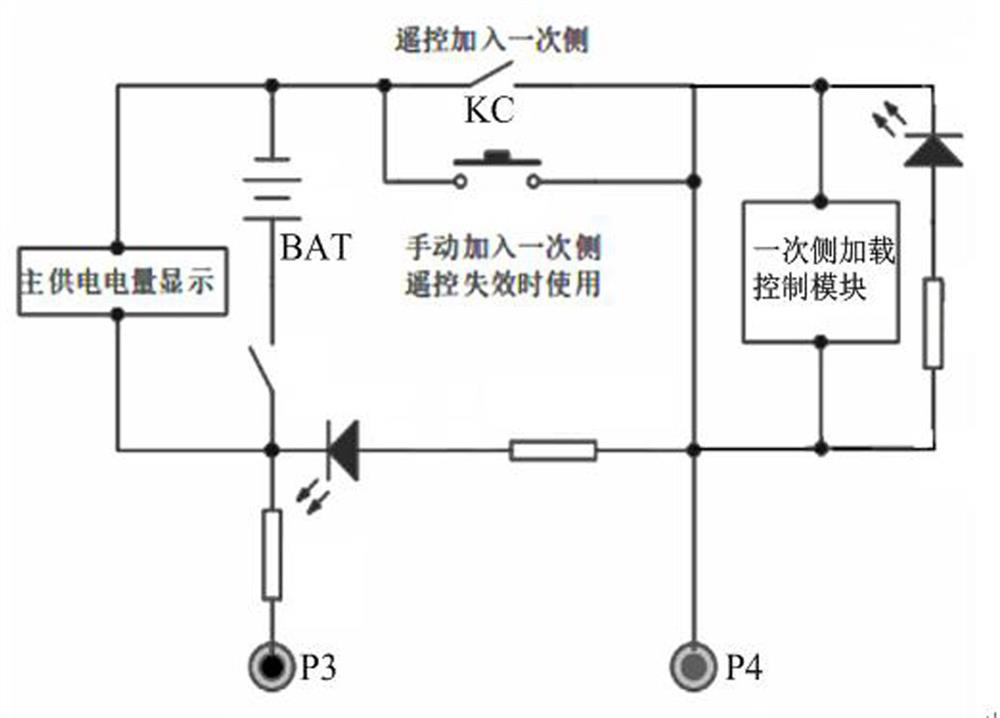
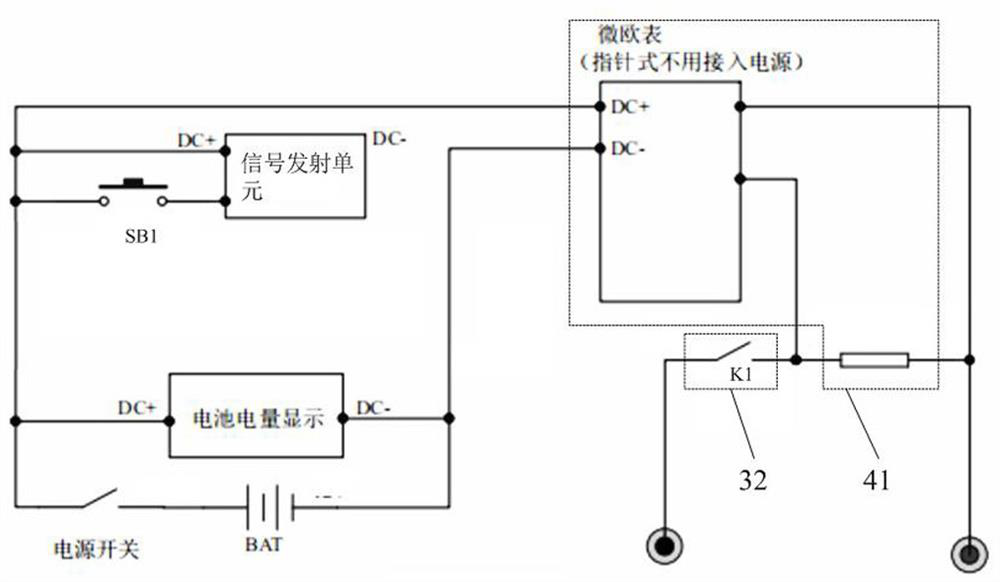
The invention discloses a polarity detection device for a current transformer, comprising a DC power supply module, a primary side loading control module, a secondary side synchronous control module, and a secondary side detection and monitoring module. 1. Power supply for each module on the secondary side, and provide discharge loading voltage to the primary side loading control module; the primary side loading control module is used to wirelessly receive the control instructions of the secondary side synchronous control module, and execute the control current transformer according to the control instructions Pressurization and loading of the primary side; the secondary side synchronous control module is used to wirelessly send control instructions to the primary side loading control module, and synchronously start the secondary side detection and monitoring module; the secondary side detection and monitoring module is used for battery power The monitoring, the polarity detection and display of the secondary measurement of the tested current transformer, realize the safe and accurate verification of the current mutual inductance polarity function, and overcome the current difficult problem of current mutual inductance polarity verification.

Description

technical field [0001] The invention relates to the technical field of transformer detection, in particular to a polarity detection device of a current transformer. Background technique [0002] The current transformer is one of the important equipment in the power system. It is widely used in secondary equipment applications such as measurement and control, relay protection, electric energy metering, and fault recording. The two important characteristics of the current transformer are transformation ratio and polarity. Whether it directly affects the accuracy of the power secondary equipment and the safe and reliable operation of the power system, so in the relevant regulations of the power system, the current transformer needs to do a polarity test before and after the handover acceptance, fixed inspection and maintenance, and before putting into operation, and all It is an important test item. [0003] At present, for the rapid detection method and instrument of current ...

Claims


Application Information

Patent Timeline
Patent Type & Authority Patents(China)
IPC IPC(8): G01R31/72G01R35/02
CPCG01R31/72G01R35/02
Inventor 张大兴黄泽荣蔡冰子尹星光甘晓瑜谢慧丽袁昊宇
Owner HUIZHOU POWER SUPPLY BUREAU OF GUANGDONG POWER GRID CO LTD
Learn More