Electrical wire insulation protection device for power plant
A technology for electrical wiring and insulation protection, which is applied to devices, electrical components, and conductive connections that reduce stress at wire connections.
- Summary
- Abstract
- Description
- Claims
- Application Information
AI Technical Summary
Problems solved by technology
Method used
Image
Examples
Embodiment 1
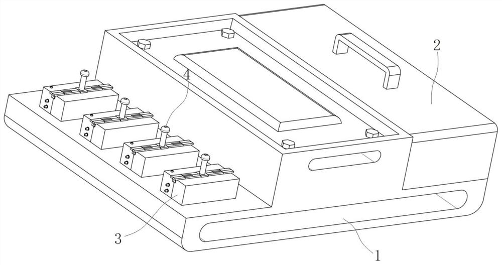
[0022] The invention provides a technical solution: an electrical wiring insulation protection device for power plants, please refer to figure 1 , including the mounting base 1 and the cover body 2;
[0023] see figure 1 , the two sets of covers 2 are installed on the top outer wall of the installation base 1, the installation base 1 is fixed in the installation area by bolts, the compensation components 3 are evenly installed on the left and right sides of the top of the installation base 1, and the top outer wall of the compensation component 3 is movably installed with wiring Column 4;
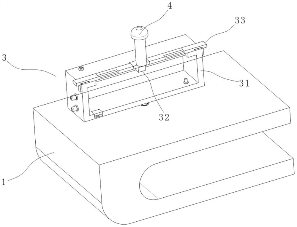
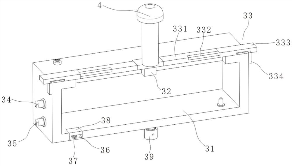
[0024] see figure 1 and figure 2 The compensation assembly 3 includes a liquid storage tank 31 installed above the mounting base 1, the inner cavity of the liquid storage tank 31 is filled with conductive liquid, the outer wall of the top of the liquid storage tank 31 is provided with a guide groove, and the inner cavity of the guide groove is slidably installed with a guide block, And...
Embodiment 2
[0028] see image 3 , on the basis of Embodiment 1, a first warning light 34 is installed on the left outer wall of the liquid storage tank 31, a conductive sheet is installed on the left inner wall of the liquid storage tank 31, and the conductive sheet is electrically connected to the first warning light 34, and The conductive sheet is located in the conductive liquid. During the process of connecting electricity, the first warning light 34 will be energized and glow when it is in contact with the conductive liquid during the power connection process. If the first warning light 34 does not emit light, then The staff can know the situation inside the liquid storage tank 31 in time;
[0029] see image 3 , the bottom of the inner cavity of the liquid storage tank 31 is provided with a placement groove 36, the inner cavity of the placement groove 36 is slidably connected with the pressure plate 38 through an elastic component, the bottom of the inner cavity of the placement gr...
Embodiment 3
[0032] see figure 2 , image 3 and Figure 4 , on the basis of Embodiment 1, a mounting sleeve 39 is installed on the outer wall of the bottom of the liquid storage tank 31, a mounting hole is opened at the connection part between the mounting seat 1 and the liquid storage tank 31, and the mounting sleeve 39 is installed in the inner cavity of the mounting hole Among them, the inner cavity of the installation sleeve 39 is connected to the rotating rod 310 through a torsion spring, and the top of the rotating rod 310 is connected to the outer wall of the bottom of the liquid storage tank 31, and the rotating rod 310 is rotated in the inner cavity of the installation sleeve 39 to make the liquid storage tank 31 It can rotate slightly above the mounting base 1, so that the liquid storage tank 31 of the compensation component 3 can rotate when the electrical wiring is being pulled, which has a compensation effect and further reduces the impact on the electrical wiring. Protect;...
PUM
 Abstract
Description
Claims
Application Information
 - R&D
- Intellectual Property
- Life Sciences
- Materials
- Tech Scout
- Unparalleled Data Quality
- Higher Quality Content
- 60% Fewer Hallucinations
Browse by: Latest US Patents, China's latest patents, Technical Efficacy Thesaurus, Application Domain, Technology Topic, Popular Technical Reports.
© 2025 PatSnap. All rights reserved.Legal|Privacy policy|Modern Slavery Act Transparency Statement|Sitemap|About US| Contact US: help@patsnap.com


