
Ambient Light Compensation Circuit for Infrared Receiver
A technology of infrared receiving and compensating circuits, which is applied in the direction of adjusting electrical variables, without intermediate conversion to AC conversion equipment, instruments, etc., and can solve the problem that the receiving device cannot apply a linear amplification system.
- Summary
- Abstract
- Description
- Claims
- Application Information
AI Technical Summary
Problems solved by technology
Method used
Image

Examples
Embodiment Construction
[0039] The present invention will be described in detail below in conjunction with the implementations shown in the drawings, but it should be noted that these implementations are not limitations of the present invention, and those of ordinary skill in the art based on the functions, methods, or structural changes made by these implementations Equivalent transformations or substitutions all fall within the protection scope of the present invention.
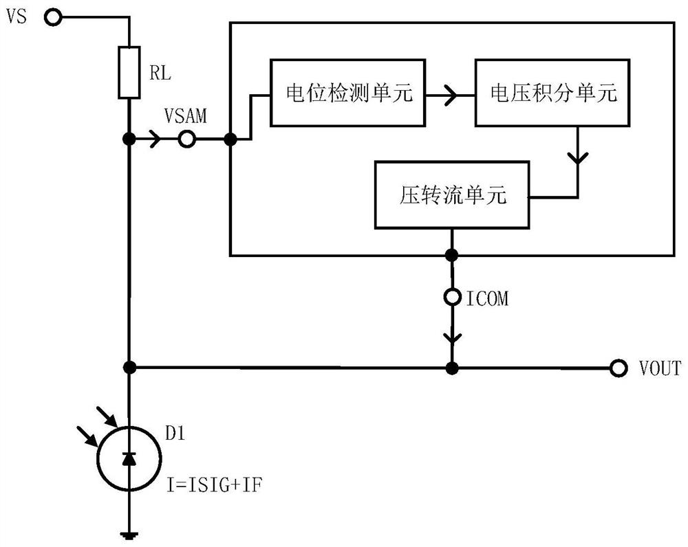
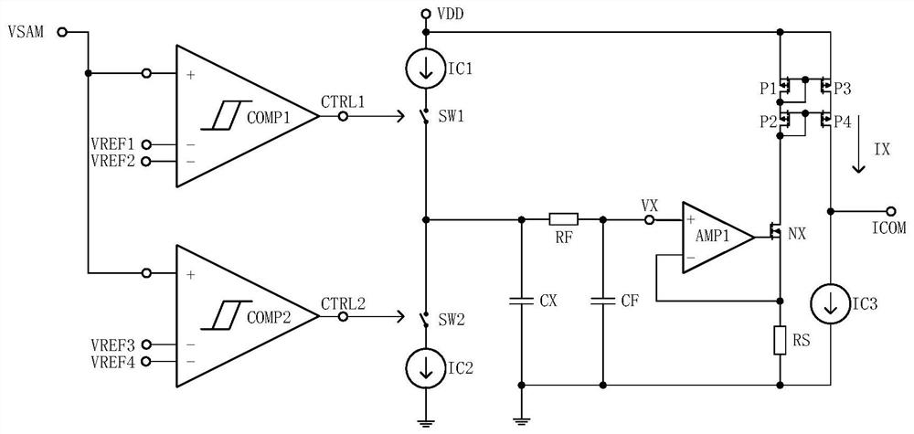
[0040] Such as figure 2 , image 3 As shown, the ambient light compensation circuit for the infrared receiving device of the present invention includes an infrared receiving diode D1 and a load resistor RL, including:
[0041]A potential detection unit, the signal input terminal of the potential detection unit is connected to the first voltage signal output terminal VSAM, and the first voltage signal output terminal VSAM is connected to the common end of the infrared receiving diode D1 and the load resistor RL, and the potential...
PUM
 Abstract
Description
Claims
Application Information