Push-pull switching power clamping circuit

A switching power supply, clamping circuit technology, applied in electrical components, adjusting electrical variables, instruments, etc., can solve the problems of poor consistency of ultrasonic oscillators, large time-varying, transformer leakage inductance, etc., to eliminate spikes and ringing signals, Simple structure and easy operation

Inactive Publication Date: 2020-01-14
ZHEJIANG BUSINESS TECH INST
View PDF4 Cites 0 Cited by
  • Summary
  • Abstract
  • Description
  • Claims
  • Application Information

AI Technical Summary

Problems solved by technology

[0002] Ultrasonic technology has been widely used in modern industry, medicine and other fields, but there are still many problems: 1. The consistency of the ultrasonic vibrator is very poor, and the time variation is too large, which makes it difficult to match the power of ultrasonic waves; 2. In order to obtain high efficiency and large Power output usually adopts a digitally driven transformer output method. Because of the transformer leakage inductance, the output power rectangular wave has various peaks and ringing voltages that are difficult to eliminate during the cut-off period of the power output module, resulting in the quality of the waveform driving the ultrasonic wave. Poor, reduces system efficiency and work effectiveness
[0003] In the prior art, the usual practice is to connect an RC series snubber circuit in parallel to the collector of the output transistor (or the drain of the field effect transistor). Although the circuit is simple and the cost is low, it can only eliminate the excessive spike caused by the leakage inductance Pulse, the ringing signal cannot be eliminated, and the output waveform is still messy

Method used


Image

  • Push-pull switching power clamping circuit
  • Push-pull switching power clamping circuit
  • Push-pull switching power clamping circuit

Examples


Embodiment Construction

[0026] The following will clearly and completely describe the technical solutions in the embodiments of the present invention with reference to the accompanying drawings in the embodiments of the present invention. Obviously, the described embodiments are only some, not all, embodiments of the present invention. Based on the embodiments of the present invention, all other embodiments obtained by persons of ordinary skill in the art without making creative efforts belong to the protection scope of the present invention.

[0027] The object of the present invention is to provide a push-pull switching power supply clamping circuit with high efficiency, simple structure and easy operation.

[0028] In order to make the above objects, features and advantages of the present invention more comprehensible, the present invention will be further described in detail below in conjunction with the accompanying drawings and specific embodiments.

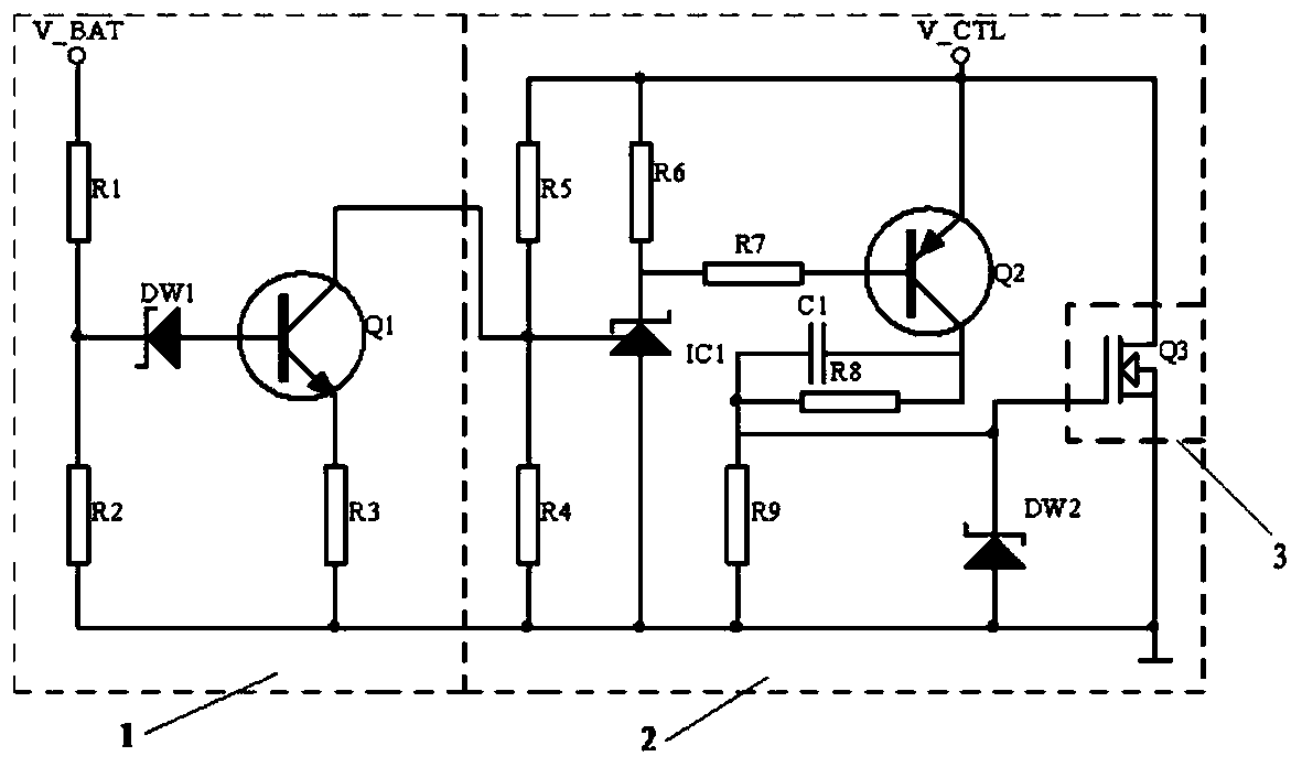
[0029] Such as figure 1 As shown, the push...


PUM


Abstract

The invention discloses a push-pull switching power clamping circuit. The circuit comprises a power compensation module, a clamping control module and a power output module; the power compensation module is connected with the clamping control module and a power supply, and is used for providing a compensated clamping control voltage for the clamping control module when the voltage of the power supply fluctuates; the clamping control module is connected with the power output module, and the clamping control module feeds back the control electrode of the power output module through the clampingcontrol voltage so as to control the clamping voltage. By means of the circuit, the peak pulses at the output end of the push-pull type power output module can be eliminated, and the ringing signals can be eliminated, so it is ensured that the push-pull type switching power supply outputs 0 without parasitizing any spurious signals when output of the power output module is cut off, and the outputwaveform is a standard rectangular wave voltage.

Description

technical field [0001] The invention relates to the technical field of clamping circuits, in particular to a push-pull switching power supply clamping circuit. Background technique [0002] Ultrasonic technology has been widely used in modern industry, medicine and other fields, but there are still many problems: 1. The consistency of the ultrasonic vibrator is very poor, and the time variation is too large, which makes it difficult to match the power of ultrasonic waves; 2. In order to obtain high efficiency and large Power output usually adopts a digitally driven transformer output method. Because of the transformer leakage inductance, the output power rectangular wave has various peaks and ringing voltages that are difficult to eliminate during the cut-off period of the power output module, resulting in the quality of the waveform driving the ultrasonic wave. Very poor, reducing system efficiency and work effect. [0003] In the prior art, the usual practice is to connec...

Claims


Application Information

Patent Timeline
Patent Type & Authority Applications(China)
IPC IPC(8): H02M3/156
CPCH02M3/156
Inventor 翁正国
Owner ZHEJIANG BUSINESS TECH INST
Why Eureka
Try Eureka