Device and method for improving motion resolution of standing wave type piezoelectric motor

A piezoelectric motor and resolution technology, applied in piezoelectric effect/electrostrictive or magnetostrictive motors, generators/motors, electrical components, etc., can solve the problems of limited application of domestic piezoelectric motors, and achieve Improved motion resolution and wide-ranging effects

Active Publication Date: 2021-11-09
INST OF MACHINERY MFG TECH CHINA ACAD OF ENG PHYSICS
View PDF3 Cites 0 Cited by
  • Summary
  • Abstract
  • Description
  • Claims
  • Application Information

AI Technical Summary

Problems solved by technology

[0005] In order to solve the problem of limited application of existing domestic piezoelectric motors, the present invention provides a motion resolution improvement device for standing wave piezoelectric motors

Method used


Image

  • Device and method for improving motion resolution of standing wave type piezoelectric motor
  • Device and method for improving motion resolution of standing wave type piezoelectric motor
  • Device and method for improving motion resolution of standing wave type piezoelectric motor

Examples


Embodiment

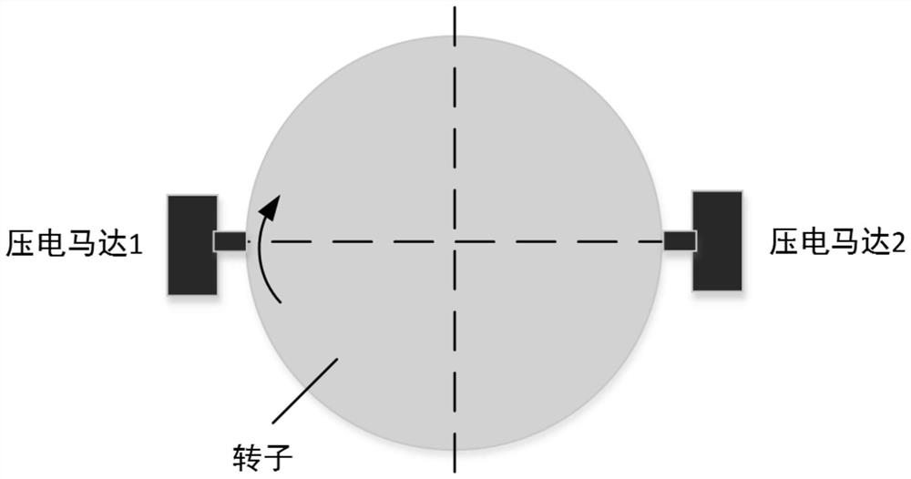
[0040] This embodiment provides a standing wave piezoelectric motor motion resolution improving device. The piezoelectric motor motion resolution improving device in this embodiment uses two groups of piezoelectric motors distributed on different driving radii to move in reverse to form a differential Motion displacement, so as to achieve the improvement of motion resolution.

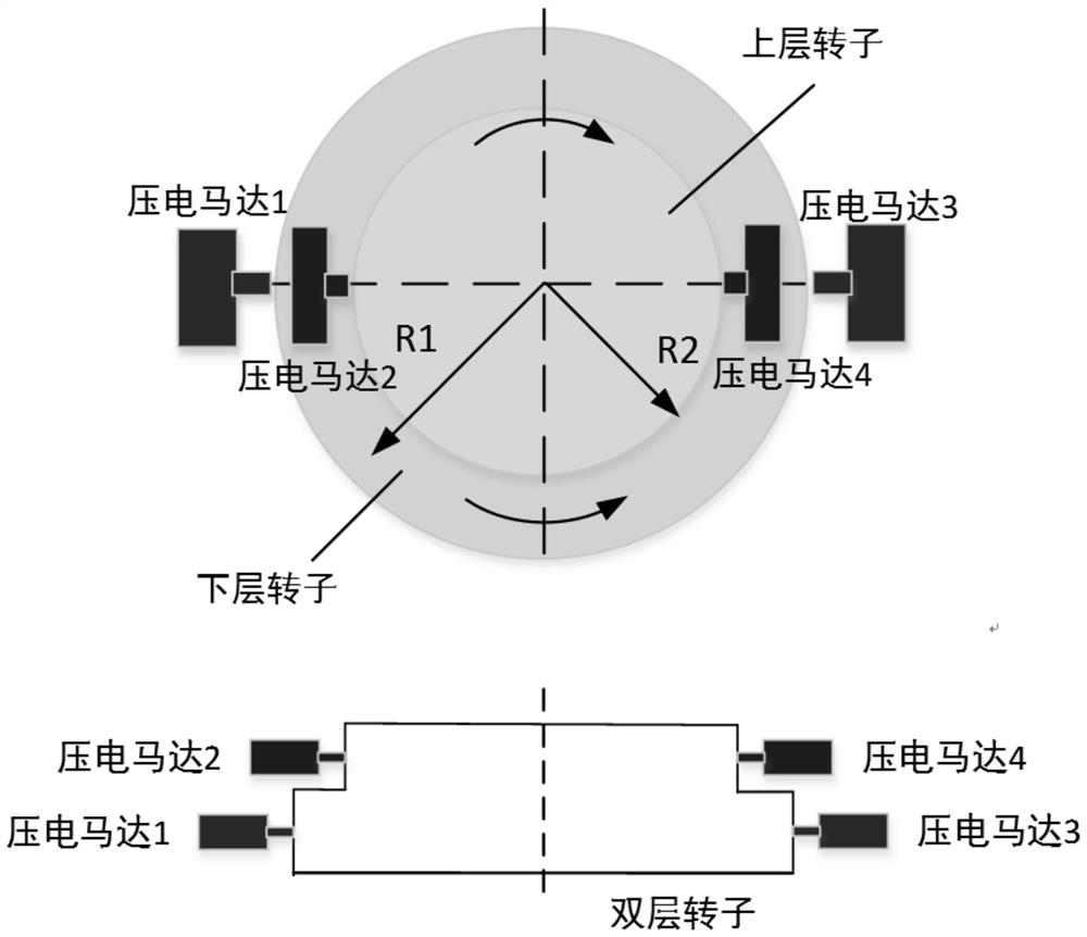
[0041] like figure 2As shown, different from the traditional piezoelectric motor drive layout, the device of this embodiment includes an upper drive structure and a lower drive structure; wherein, the upper drive structure includes an upper rotor, and an upper piezoelectric motor set uniformly installed along the circumferential side of the upper rotor. The driving structure of the lower layer includes the lower layer rotor and the lower layer piezoelectric motor set uniformly installed along the circumference side of the lower layer rotor; The rotor rotates counterclockwise under the drive of the low...

Embodiment 2

[0052] The difference between this embodiment and the above-mentioned Embodiment 1 is that the four sets of piezoelectric motors in this embodiment are evenly distributed on the circumferential side (that is, two adjacent sets of piezoelectric motors, one of which is arranged on the upper rotor side, and the other is arranged on the upper rotor side). on the lower rotor side), such as Figure 4 shown.

[0053] The step resolution of the piezoelectric motor in this embodiment is λ=50nm, the piezoelectric motor 1 and the piezoelectric motor 3 are symmetrically installed in the lower position, and the driving diameter is R 1 =280mm, the angular step resolution is Piezoelectric motor 2 and piezoelectric motor 4 are symmetrically installed on the upper position, and the driving diameter is R 2 =200mm, the angular step resolution is First, the upper piezoelectric motor 2 and piezoelectric motor 4 are powered on, and the lower piezoelectric motor 1 and piezoelectric motor 3 are ...

Embodiment 3

[0055] The difference between this embodiment and the above-mentioned embodiment 2 only includes that in this embodiment, six sets of piezoelectric motors are used in staggered layers and evenly distributed on the circumference side, that is, the upper piezoelectric motor group includes 3 sets of piezoelectric motors (piezoelectric motor 2, piezoelectric motor Electric motor 4 and piezoelectric motor 6), the lower piezoelectric motor group includes 3 sets of piezoelectric motors (piezoelectric motor 1, piezoelectric motor 3 and piezoelectric motor 5), two adjacent sets of piezoelectric motors, one of which Arranged on the side of the upper rotor, and another set is arranged on the side of the lower rotor, such as Figure 5 shown.

[0056] The stepping resolution of the piezoelectric motor in this embodiment is λ=50nm, the piezoelectric motor 1, the piezoelectric motor 3 and the piezoelectric motor 5 are evenly installed on the circumference of the lower rotor, and the driving ...


PUM


Abstract

The invention discloses a device and a method for improving the motion resolution of a standing wave type piezoelectric motor. The device comprises an upper-layer driving structure and a lower-layer driving structure; the upper-layer driving structure comprises an upper-layer rotor and upper-layer piezoelectric motor groups which are symmetrically arranged on the circumferential side of the upper-layer rotor along the circle center of the upper-layer rotor; the lower-layer driving structure comprises a lower-layer rotor and lower-layer piezoelectric motor groups which are symmetrically arranged on the circumferential side of the lower-layer rotor along the circle center of the lower-layer rotor, and each of the upper-layer piezoelectric motor group and the lower-layer piezoelectric motor group comprises N piezoelectric motors; the upper layer rotor and the lower layer rotor are coaxially arranged, the upper layer rotor is driven by the upper layer piezoelectric motor group to rotate in the clockwise direction, and the lower layer rotor is driven by the lower layer piezoelectric motor group to rotate in the anticlockwise direction. According to the invention, two groups of piezoelectric motors distributed on different driving radiuses move in opposite directions to form differential displacement, so the motion resolution is improved.

Description

technical field [0001] The invention belongs to the technical field of precision actuation, and in particular relates to a device and method for improving motion resolution of a standing wave piezoelectric motor. Background technique [0002] The piezoelectric motor is a new type of micro-actuator. Its principle is to use the inverse piezoelectric effect of piezoelectric ceramics and the ultrasonic vibration of the elastic body to convert the microscopic deformation into the macroscopic deformation of the mover or slider through resonance amplification and electromechanical coupling. sports. Because the piezoelectric motor has the advantages of low speed and high resolution, and can rely on static friction to keep the motor output shaft self-locking when there is no signal input, it has been well applied in the fields of precision machinery and automatic control. According to its driving mechanism, it can be divided into traveling wave type, surface acoustic wave type and s...

Claims


Application Information

Patent Timeline
Patent Type & Authority Applications(China)
IPC IPC(8): H02N2/10H02N2/12H02N2/14
CPCH02N2/101H02N2/123H02N2/14
Inventor 胡秋李梦阳王佳昌张日升
Owner INST OF MACHINERY MFG TECH CHINA ACAD OF ENG PHYSICS
Why Eureka
Try Eureka