
Sound cavity support and terminal device

A technology of terminal equipment and sound cavity, applied in branch equipment, telephone structure, telephone communication, etc., can solve problems such as preempting space, and achieve the effect of ensuring integrity, avoiding audio performance loss, and improving audio effect.

Pending Publication Date: 2021-11-09
ANHUI ANUKI TECH CO LTD
View PDF0 Cites 1 Cited by
  • Summary
  • Abstract
  • Description
  • Claims
  • Application Information

AI Technical Summary

Problems solved by technology

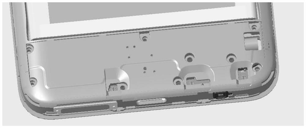
[0003] In the prior art, in order to reduce the radiation of the antenna to the human body, the main antenna of the current mobile phone is mostly installed at the bottom of the mobile phone, and considering the audio effect, the audio output is also installed at the bottom of the mobile phone, often causing two functional modules to occupy space with each other

Method used


Image

  • Sound cavity support and terminal device
  • Sound cavity support and terminal device
  • Sound cavity support and terminal device

Examples


Embodiment Construction

[0025] In order to make the purposes, technical solutions and advantages of the embodiments of the present application clearer, the technical solutions in the embodiments of the present application will be clearly and completely described below in conjunction with the drawings in the embodiments of the present application. Obviously, the described embodiments It is a part of the embodiments of this application, not all of them. The components of the embodiments of the application generally described and illustrated in the figures herein may be arranged and designed in a variety of different configurations.

[0026] Accordingly, the following detailed description of the embodiments of the application provided in the accompanying drawings is not intended to limit the scope of the claimed application, but merely represents selected embodiments of the application. Based on the embodiments in this application, all other embodiments obtained by persons of ordinary skill in the art w...


PUM


Abstract

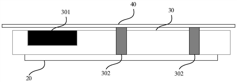
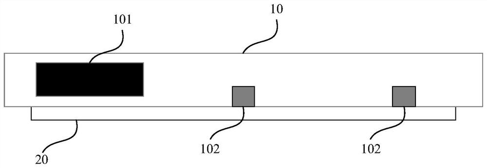
The invention provides a sound cavity support and terminal equipment. A sound cavity is arranged in the sound cavity bracket, the sound cavity is used for installing a loudspeaker, a part of the sound cavity bracket is used as an antenna unit, and the antenna unit is connected with a mainboard; the sound cavity bracket is a conductive bracket. No extra reserved space is needed for mounting the antenna, and the original space for mounting the antenna can be used as a part of the sound cavity bracket, so that the space size of the sound cavity bracket can be increased. Furthermore, the size of the sound cavity arranged in the sound cavity bracket can be increased, and the audio effect is improved. And secondly, the sound cavity bracket cannot be damaged by the antenna, so that the integrity of the sound cavity bracket is guaranteed, and the audio performance loss is avoided.

Description

technical field [0001] The present application relates to the field of electronic equipment, in particular, to a sound cavity support and terminal equipment. Background technique [0002] With the development of society and the advancement of science, more and more electronic devices are applied to people's lives, especially the popularity of smart phones is very high. Taking the mobile phone as an example, as the function and appearance of the mobile phone are continuously upgraded, the screen ratio of the mobile phone is getting larger and larger, the thickness of the mobile phone is getting thinner and thinner, and it is more and more difficult to debug the antenna inside the mobile phone. [0003] In the prior art, in order to reduce the radiation of the antenna to the human body, the main antenna of the current mobile phone is mostly installed at the bottom of the mobile phone, and considering the audio effect, the audio output is also installed at the bottom of the mob...

Claims


Application Information

Patent Timeline
Patent Type & Authority Applications(China)
IPC IPC(8): H04M1/03H04M1/02
CPCH04M1/03H04M1/026
Inventor 徐雷左成杰何军
Owner ANHUI ANUKI TECH CO LTD
Learn More