Anti-swing positioning crane
A crane and anti-sway technology, applied in the direction of clockwork mechanism, load hanging components, safety devices, etc., can solve the problems of shaking of goods, inability to stop goods in positioning, poor anti-sway effect, etc., and achieve convenient positioning , The effect of reducing the risk of falling and reducing the chance of shaking
- Summary
- Abstract
- Description
- Claims
- Application Information
AI Technical Summary
Problems solved by technology
Method used
Image

Examples
Embodiment 1
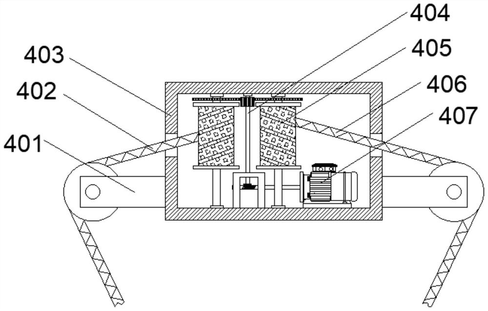
[0031] Above-mentioned hoisting mechanism 4 comprises shell 403 that is movably connected with cantilever 5, and pulley 401 is all fixedly installed on the outer wall of both sides of shell 403, and the inside of shell 403 is provided with cavity, and the inside of cavity is provided with transmission mechanism 404, and transmission mechanism 404 Both sides of the cavity are provided with a winding mechanism 405, and the bottom of the cavity is fixed with a first servo motor 407 by bolts.
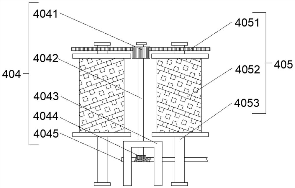
[0032] The above-mentioned transmission mechanism 404 includes a mounting frame 4043 fixedly connected to the bottom of the cavity wall of the casing 403, a worm 4045 is arranged on one side of the mounting frame 4043, one end of the worm 4045 moves through the mounting frame 4043, and the other end of the worm 4045 is connected to the second The output end of a servo motor 407 is fixedly connected, the top of the mounting frame 4043 is provided with a first rotating shaft 4042, the bottom e...
Embodiment 2
[0036] The above-mentioned guide mechanism 2 includes a first fixed plate 201 and a second fixed plate 203 fixedly connected with the support frame 1, a guide rod 206 is fixedly connected between the first fixed plate 201 and the second fixed plate 203, and slides on the guide rod 206 A guide sleeve 202 is provided on the sleeve, a moving mechanism 207 is provided on one side of the guide sleeve 202, and a fixed seat 205 is fixedly installed on the other side of the guide sleeve 202, and a traction rope 204 is fixedly connected to the fixed seat 205.
[0037] The above-mentioned moving mechanism 207 includes an installation box 2071 fixedly connected with the guide sleeve 202. The inside of the installation box 2071 is fixed with a second servo motor 2072 by bolts, and the output end of the second servo motor 2072 is fixedly connected with a third rotating shaft 2073. One end of the three rotating shafts 2073 moves through the installation box 2071 and one side wall of the guide ...
Embodiment 3
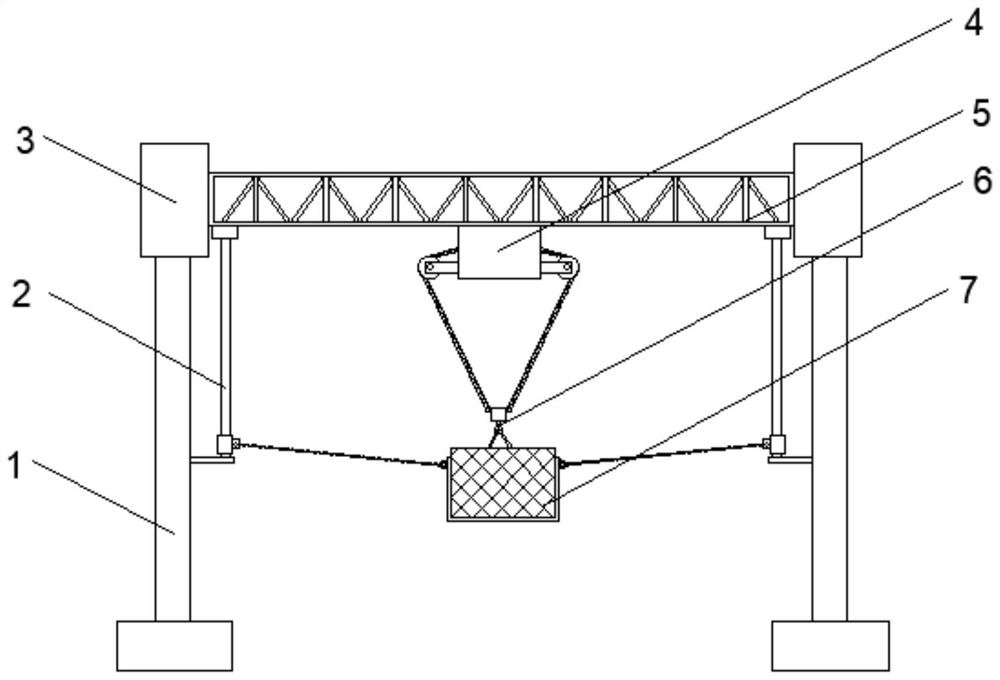
[0040] The above-mentioned support mechanism 7 includes a placement plate 703 arranged below the lifting mechanism 4, and both ends of the placement plate 703 are fixedly connected with a fixed ring 702, and the two fixed rings 702 are sleeved with a first hook 701, and the two first hooks 701 is respectively fixedly connected with two traction ropes 204, and the top surface of the placement plate 703 is placed with goods 704; the two traction ropes 204 cooperate with the guide bar 206, the first fixed plate 201 and the second fixed plate 203 to play a role for the goods 704. The protective effect is to prevent that after the first lifting rope 402 and the second lifting rope 406 are broken, the goods 704 directly fall down and cause damage to people or other buildings below.
[0041] Both the bottom ends of the first lifting rope 402 and the second lifting rope 406 are fixedly connected with the second hook 6 , and the second hook 6 is fixedly connected with the top of the car...
PUM
 Abstract
Description
Claims
Application Information
 - R&D
- Intellectual Property
- Life Sciences
- Materials
- Tech Scout
- Unparalleled Data Quality
- Higher Quality Content
- 60% Fewer Hallucinations
Browse by: Latest US Patents, China's latest patents, Technical Efficacy Thesaurus, Application Domain, Technology Topic, Popular Technical Reports.
© 2025 PatSnap. All rights reserved.Legal|Privacy policy|Modern Slavery Act Transparency Statement|Sitemap|About US| Contact US: help@patsnap.com