Lighting device and vehicle lamp

A lighting device and a technology for installing grooves, which are applied in the field of lighting, can solve problems such as the influence of lighting light distribution of automobile lights, poor structural stability of light guide elements, etc., and achieve the effects of simple and reliable fixed structure, avoiding sliding, and facilitating processing and assembly

Pending Publication Date: 2021-11-12
YLX INC
View PDF0 Cites 0 Cited by
  • Summary
  • Abstract
  • Description
  • Claims
  • Application Information

AI Technical Summary

Problems solved by technology

Compared with traditional automotive light sources such as tungsten filament lamps, the light-emitting device and the light guide element of the simulated filament LED lighting device are separated from each other, and the light guide element is in the shape of a strip, so the structural stability of the light guide element is poor, and the vibration of the car It is easy to change the relative position of the light guide element and the light-emitting device, which has a huge impact on the lighting distribution of the car lights

Method used


Image

  • Lighting device and vehicle lamp
  • Lighting device and vehicle lamp
  • Lighting device and vehicle lamp

Examples


Embodiment 1

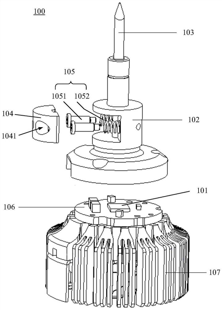
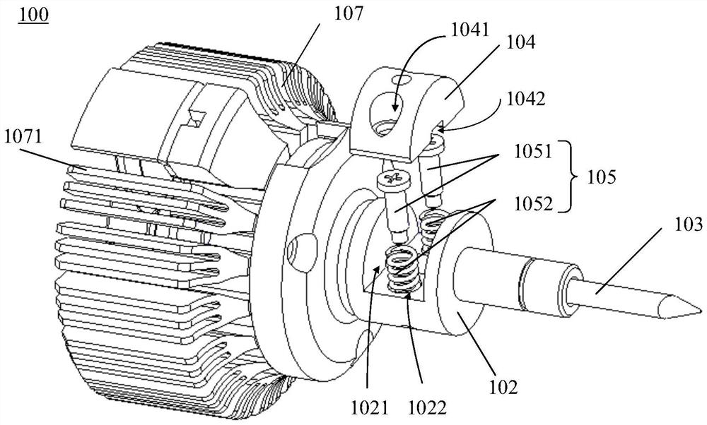
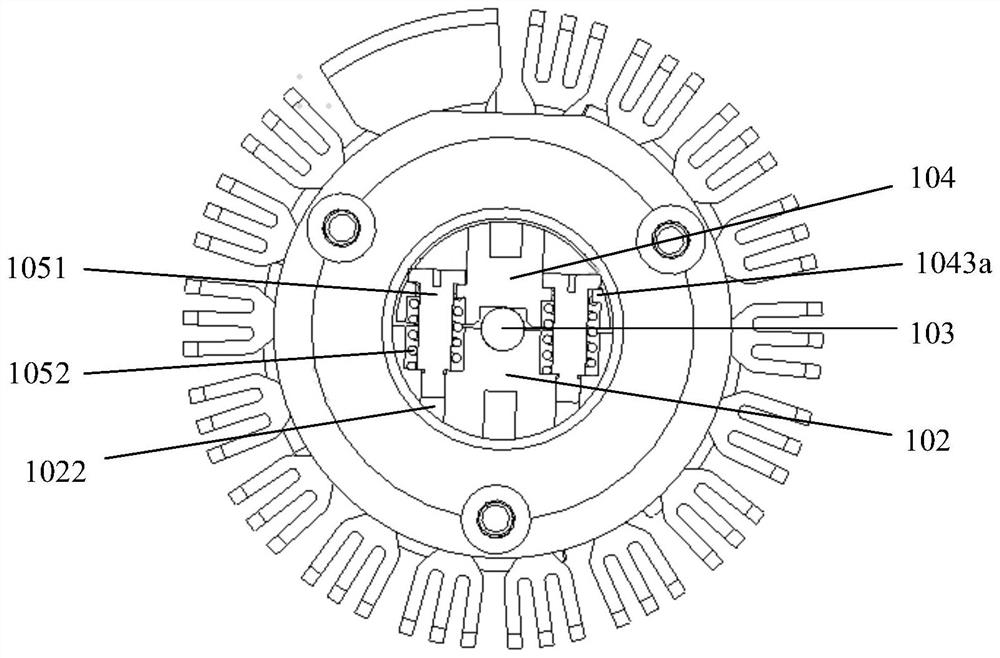
[0033] See figure 1 and figure 2 , figure 1 and figure 2 It is a schematic structural diagram of the lighting device 100 provided by Embodiment 1 of the present invention. The lighting device 100 includes a light emitting device 101 , a housing 102 , a light guide rod 103 , a fixing piece 104 , and an elastic component 105 .

[0034] The housing 102 is provided with a mounting hole and a mounting groove 1021 communicating with the mounting hole. The light guide rod 103 is inserted in the mounting hole. One end of the light guide rod 103 is the light incident surface, and the other end is the light exit surface. The light-emitting device 101 is opposite, and the light emitted by the light-emitting device 101 enters the light guide rod 103 through the light-incident surface, and exits from the light-exit surface; The component 105 is connected, and the elastic component 105 is elastically deformed so that the fixing member 104 fixes the light guide rod.

[0035] Compared w...

Embodiment 2

[0052] Please refer to Figure 7 and Figure 8 , Figure 7 It is a schematic structural diagram of the lighting device 200 provided by Embodiment 2 of the present invention, Figure 8 It is a schematic diagram of the fixing structure of the light guide rod 103 of the lighting device 200 in the second embodiment of the present invention. The components in this embodiment that are the same as those in Embodiment 1 are denoted by the same serial numbers. The difference between this embodiment and Embodiment 1 is that the mounting groove 2021 on the housing 202 is a threaded hole, the fixing piece 204 is in the shape of a sheet, which is made of rigid metal material, and can be placed in the mounting groove 2021, and the connecting piece 2051 As a stud matching the mounting groove 2021, the connecting piece 2051 is threadedly connected to the mounting groove 2021, so that the connecting piece 2051 is fixed on the housing 202, the elastic piece 2052 is arranged between the conne...

Embodiment 3

[0056] Please refer to Figure 9 and Figure 10 , Figure 9 It is a schematic structural diagram of the lighting device 300 provided by Embodiment 3 of the present invention, Figure 10 It is a schematic diagram of the fixing structure of the light guide rod 103 of the lighting device 300 in the second embodiment of the present invention. The components in this embodiment that are the same as those in Embodiment 1 are denoted by the same serial numbers. The difference between this embodiment and Embodiment 1 is that the installation groove 3021 on the housing 302 is a threaded hole, the fixing piece 304 is in the shape of a sheet, which is made of rigid metal material and can be placed in the threaded hole, and the connecting piece 3051 is The stud matching the threaded hole, the connecting piece 3051 is threadedly connected with the mounting groove 3021 , so that the connecting piece 3051 is fixed on the housing 302 , and the elastic piece 3052 is a spring, which is arrang...


PUM


Abstract

The invention provides a lighting device and a vehicle lamp. The lighting device comprises a light-emitting device, a shell, a light guide bar and a fixing piece. A mounting hole and a mounting groove communicating with the mounting hole are formed in the shell, the light guide rod penetrates through the mounting hole, one end of the light guide rod is a light-in surface, the other end of the light guide rod is a light-out surface, the light-in surface is opposite to the light-emitting device, and light emitted by the light-emitting device enters the light guide rod through the light-in surface and is emitted from the light-out surface; and the fixing piece is installed in the mounting groove and connected with an elastic assembly arranged on the shell, and the elastic assembly elastically deforms so that the fixing piece can fix the light guide bar. The fixing structure of the light guide rod is simple, reliable and good in stability.

Description

technical field [0001] The invention relates to the technical field of lighting, in particular to a lighting device and a vehicle lamp. Background technique [0002] The lamps on the vehicle are an important factor affecting the driving safety of the vehicle. The development of the automobile industry has put forward higher and higher requirements for the vehicle lamps. Tungsten filament lamps are a common light source for automotive lighting, but they are gradually being eliminated due to their low brightness, high energy consumption, and insufficient lifespan. In order to improve the brightness of the light source and reduce energy consumption, researchers have begun to develop an LED lighting device that simulates the application of a filament. . The simulated filament LED lighting device has the same luminous characteristics as the tungsten filament lamp, and has the advantages of high brightness and long life, so it can replace the tungsten filament lamp and be used i...

Claims


Application Information

Patent Timeline
Patent Type & Authority Applications(China)
IPC IPC(8): F21V17/16F21V17/12F21W107/10F21Y115/10F21Y115/30
CPCF21V17/16F21V17/12F21W2107/10F21Y2115/10F21Y2115/30F21S41/24
Inventor 付锦江陈彬陈康俊
Owner YLX INC
Why Eureka
Try Eureka