
Method and system for detecting refractive index distribution of self-focusing lens finished product

A technology of self-focusing lens and refractive index distribution, which is applied in the field of refractive index detection, can solve problems such as slice thickness error, lower detection efficiency, and low detection accuracy, so as to overcome environmental interference, increase detection efficiency, and avoid excessive optical components. many effects

Active Publication Date: 2021-11-12
高视科技(苏州)股份有限公司
View PDF7 Cites 0 Cited by
  • Summary
  • Abstract
  • Description
  • Claims
  • Application Information

AI Technical Summary

Problems solved by technology

[0004] The existing technology titled "A Refractive Index Distribution Testing Device and Image Acquisition Device for Self-focusing Lens" uses the Mach-Zehnder interference principle to detect the refractive index distribution of self-focusing lens slices. Slicing the lens not only reduces the detection efficiency, but also introduces the thickness error of the slice; the Mach-Zehnder interferometer uses a split light path to interfere with the light path, and the detection result is easily affected by the environment, resulting in low detection accuracy
[0005] Therefore, in the prior art, the problems of low detection efficiency and low precision caused by slicing the self-focusing lens and using split light paths to interfere with light paths need to be solved urgently.

Method used


Image

  • Method and system for detecting refractive index distribution of self-focusing lens finished product
  • Method and system for detecting refractive index distribution of self-focusing lens finished product
  • Method and system for detecting refractive index distribution of self-focusing lens finished product

Examples


Embodiment Construction

[0060] The present invention will be further described in detail below in conjunction with the accompanying drawings, and the aforementioned and other objects, features, aspects and advantages of the present invention will become more apparent, so that those skilled in the art can implement them with reference to the description. In the drawings, the shapes and dimensions may be exaggerated for clarity, and the same reference numerals will be used throughout to designate the same or like parts. In the following description, terms such as center, thickness, height, length, front, back, rear, left, right, top, bottom, upper, lower, etc. are based on the orientation or positional relationship shown in the drawings. In particular, "height" corresponds to the dimension from top to bottom, "width" corresponds to the dimension from left to right, and "depth" corresponds to the dimension from front to back. These relative terms are for convenience of description and are generally not ...


PUM


Abstract

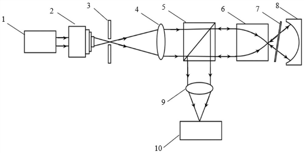
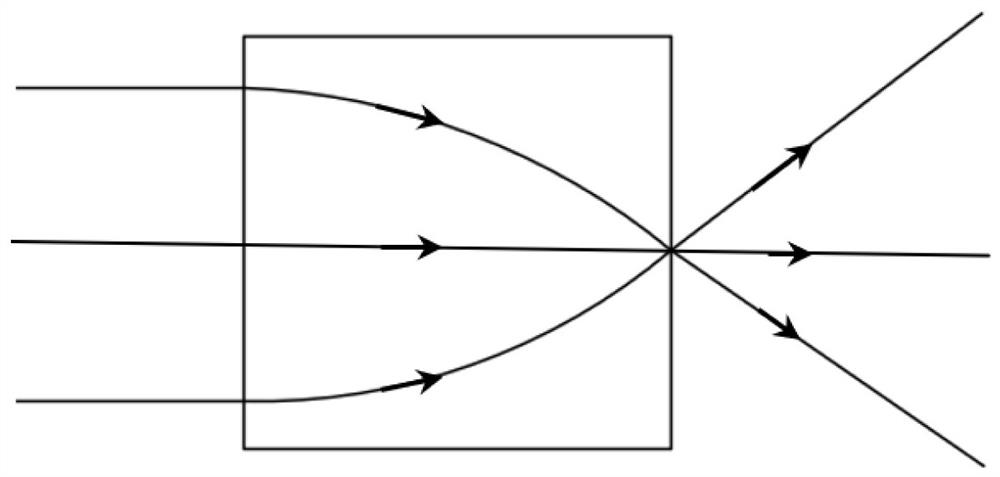
According to a method and system for detecting refractive index distribution of a self-focusing lens finished product provided by the invention, through the design of a laser light path structure, the self-focusing lens does not need to be sliced, the self-focusing lens finished product is directly detected, and the detection efficiency of the self-focusing lens refractive index distribution is improved; a reference light beam and a test light beam share a light path and belong to a Fizeau interference light path, and the refractive index distribution of the self-focusing lens is analyzed by adopting interference fringes of reflected light of the front surface of the self-focusing lens and reflected light of the standard spherical mirror, so that the problem of excessive optical elements in a traditional self-focusing lens refractive index distribution detection method is avoided; and the influence of deviation of other optical elements on the optical path difference is almost the same, so that the interference of the environment can be overcome.

Description

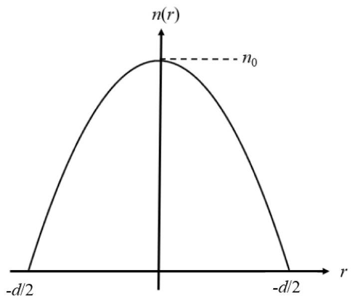
technical field [0001] The invention relates to the technical field of refractive index detection, in particular to a method and system for detecting the refractive index distribution of a self-focusing lens product. Background technique [0002] The self-focusing lens is a cylindrical optical element whose refractive index changes gradually along the radial direction. Due to its unique refractive index distribution characteristics, it has a wide range of applications in the fields of micro-optical imaging systems, medical equipment, and fiber coupling. [0003] Its optical performance depends on its refractive index distribution. Therefore, it is one of the problems studied by researchers in this field to propose a high-efficiency and high-precision detection method for the refractive index distribution of the finished self-focusing lens. [0004] The existing technology titled "A Refractive Index Distribution Measuring Device and Image Acquisition Device for Self-focusing ...

Claims


Application Information

Patent Timeline
Patent Type & Authority Applications(China)
IPC IPC(8): G01M11/02G01N21/45
CPCG01M11/0228G01N21/45
Inventor 不公告发明人
Owner 高视科技(苏州)股份有限公司
Learn More