
New energy motor power system practical training platform

A power system and training platform technology, applied in the direction of motor generator testing, measuring electricity, measuring electrical variables, etc., can solve problems affecting normal driving, etc., and achieve obvious beneficial effects

Inactive Publication Date: 2021-11-12
杨小松
View PDF0 Cites 0 Cited by
  • Summary
  • Abstract
  • Description
  • Claims
  • Application Information

AI Technical Summary

Problems solved by technology

[0003] The purpose of the present invention is to solve the shortcomings in the prior art that the vibration of the motor can easily cause slippage between the output end of the motor and the belt, thus affecting the normal drive, and proposes a new energy motor power system training platform

Method used


Image

  • New energy motor power system practical training platform
  • New energy motor power system practical training platform
  • New energy motor power system practical training platform

Examples


Embodiment 1

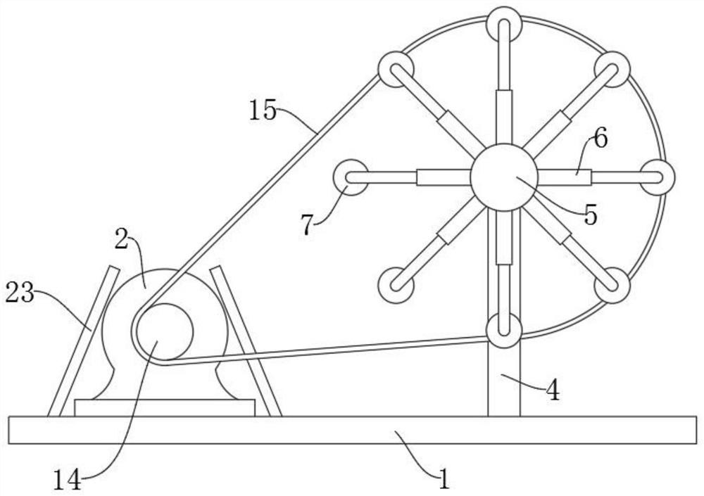
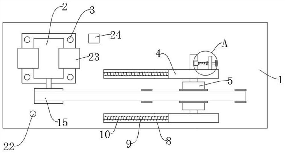
[0020] refer to Figure 1-4 , a new energy motor power system training platform, including a base 1 and a motor 2 installed on the base 1, the four corners of the motor 2 are provided with fixing holes 3, and the fixing holes 3 are matched with threaded connections on the base 1, the base 1 is provided with a driving force detection mechanism, the base 1 is fixedly connected with a swash plate 23, the shell of the motor 2 is matched with the inner side wall of the swash plate 23, and the inner side wall of the swash plate 23 is fixedly provided with A thin-film pressure sensor, a horn 24 is fixedly installed on the base 1, and a speed sensor 22 is fixedly installed on the base 1 close to the output end of the motor 2, which can be used to measure the rotation speed of the motor 2, by setting a swash plate 23 near the motor 2 , the inner wall of the swash plate 23 is fit with the gap between the motor 2 shell, and the inner wall of the swash plate 23 is fixedly provided with a ...

Embodiment 2

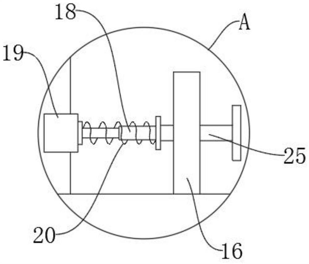
[0022] refer to Figure 1-4 , as another preferred embodiment of the present invention, the difference from Embodiment 1 is that the driving force detection mechanism includes a bracket 4, a rotating shaft 5, an electric telescopic rod 6 and a transmission wheel 7, the bracket 4 is slidably arranged on the base 1 and the bracket 4 There is a passive drive mechanism between the base 1, the rotating shaft 5 is set on the top of the bracket 4, the number of electric telescopic rods 6 is fixed on the outer wall of the rotating shaft 5 at an equal angle, and the transmission wheel 7 is fixedly connected to the electric telescopic rod 6 One end away from the rotating shaft 5, the output end of the motor 2 is fixedly connected with a synchronous pulley 14, and a belt 15 is sleeved between the transmission wheel 7 and the synchronous pulley 14. Under the action of the electric telescopic rod 6, the transmission wheel 7 and the rotating shaft 5 The distance between them is adjustable, ...


PUM


Abstract

The invention relates to the technical field of motor detection, in particular to a new energy motor power system practical training platform which comprises a base and a motor installed on the base, fixing holes are formed in the four corners of the motor in a penetrating mode, fixing bolts connected to the base in a threaded mode are arranged in the fixing holes in a matched mode, and a driving force detection mechanism is arranged on the base. An inclined plate is fixedly connected to the base, a shell of the motor is in clearance fit with the inner side wall of the inclined plate, a film pressure sensor is fixedly arranged on the inner side wall of the inclined plate, and a loudspeaker is fixedly installed on the base. The defect that in the prior art, due to vibration of a motor, the output end of the motor and a belt are prone to sliding, and normal driving is affected is overcome, the beneficial effect is obvious, and the motor is suitable for popularization.

Description

technical field [0001] The invention relates to the technical field of motor detection, in particular to a new energy motor power system training platform. Background technique [0002] New energy vehicles refer to vehicles that use unconventional vehicle fuels as power sources, integrate advanced technologies in vehicle power control and drive, and form vehicles with advanced technical principles, new technologies, and new structures. The motor in the existing new energy vehicle is a very important component in the auto parts. Whether the car can run depends entirely on the control of the motor inside the car. Therefore, when each motor is put into use, it needs to go through a long-term experiment. Most of the motor power training devices are used to detect the service life of the motor and the pulling strength of the motor. However, the motor is installed in the car as a driving structure. It must be ensured that the motor vibrates very slightly when it is running, becaus...

Claims


Application Information

Patent Timeline
Patent Type & Authority Applications(China)
IPC IPC(8): G01R31/34G01R1/04G01D21/02
CPCG01R31/343G01D21/02G01R1/0408
Inventor 杨小松
Owner 杨小松
Learn More