
Method, device and system for correcting LED lamp panel

A technology of LED light board and calibration method, applied in static indicators, instruments, etc., can solve problems such as affecting calibration efficiency, inaccurate point positioning, and increasing difficulty in point positioning, and achieve the effect of improving calibration efficiency

Pending Publication Date: 2021-11-12
XIAN NOVASTAR TECH
View PDF5 Cites 0 Cited by
  • Summary
  • Abstract
  • Description
  • Claims
  • Application Information

AI Technical Summary

Problems solved by technology

Due to the small spacing between the dots on the LED light board, the LED light points in the full-brightness correction image of the same color LED light points collected when performing color correction on the LED light board, such as brightness correction or brightness chromaticity correction, are relatively dense, resulting in subsequent The difficulty of point positioning in the image processing process increases, and in severe cases, it will cause inaccurate point positioning, which will affect the correction efficiency

Method used


Image

  • Method, device and system for correcting LED lamp panel
  • Method, device and system for correcting LED lamp panel
  • Method, device and system for correcting LED lamp panel

Examples


no. 1 example

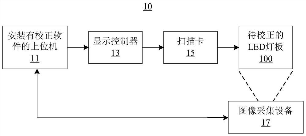
[0029] The first embodiment of the present invention provides a method for calibrating LED lamp panels, which is suitable, for example, to adopt figure 1 A calibration system 10 for an LED lamp panel is shown. Such as figure 1 As shown, the correction system 10 includes: a host computer 11 installed with correction software, a display controller 13, a scanning card 15 and an image acquisition device 17, which can be used for color correction such as brightness correction or brightness correction of the LED lamp panel 100 to be corrected. Brightness and chroma correction. In this embodiment, the upper computer 11 is, for example, a PC (Personal Computer) installed with calibration software, and the installed calibration software is, for example, NovaCLB software developed by Xi'an Nova Nebula Technology Co., Ltd. or other similar software. Furthermore, the host computer 11 can send an image display signal to the LED light board 100 through the sequentially connected display c...

no. 2 example

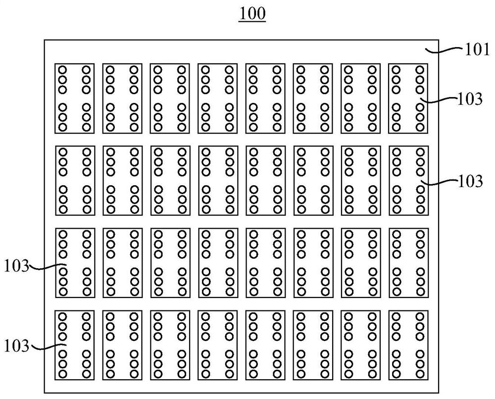
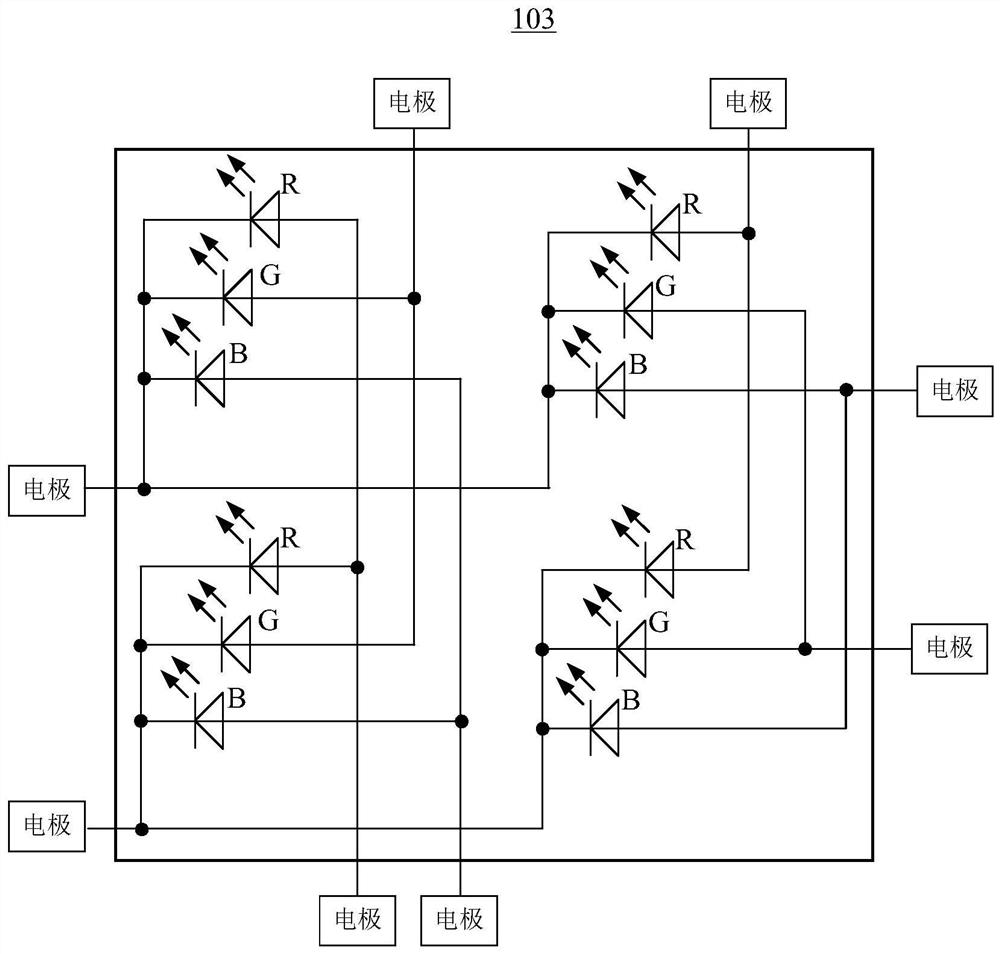
[0044] see Figure 7 , a calibration device 70 for an LED light board provided by an embodiment of the present invention, the LED light board includes a circuit board and a plurality of chip-on-board LED modules welded on the circuit board, each of the chip-on-board The type LED module includes N×M LED pixels that are independently controlled and arranged in rows and columns, N and M are positive integers greater than or equal to 2, and the N×M LED pixels correspond to N×M pixel positions respectively, and Each of the LED pixels includes multiple LEDs of different colors; the calibration device 70 includes: a display control module 71 , an acquisition control module 73 and a coefficient generation module 75 .

[0045] Wherein, the display control module 71 is, for example, used to control the plurality of chip-on-board LED modules to display a plurality of correction images in a target lighting manner, wherein the target lighting manner includes: controlling the lighting of th...


PUM


Abstract

The embodiment of the invention relates to a method, a device and a system for correcting an LED (light-emitting diode) lamp panel, which adopt a specific lightening control mode for the LED lamp panel using COB (chip on board) type LED modules as light-emitting units, i.e., LEDs with the same color of LED pixels at the same pixel position in N * M pixel positions of a plurality of COB type LED modules are controlled to be lightened every time so as to display one of a plurality of corrected images, a plurality of LED pixels, which are respectively positioned at the N * M pixel positions, of each COB type LED template are sequentially controlled to be lightened so as to display the plurality of corrected images; therefore, as the pixel point spacing of the LED lamp panel becomes smaller and smaller, a more accurate point positioning result can still be obtained, and the correction efficiency can be further improved.

Description

technical field [0001] The invention relates to the technical field of display calibration, in particular to a calibration method for an LED lamp panel, a calibration device for an LED lamp panel, and a calibration system for an LED lamp panel. Background technique [0002] With the rapid development of the LED industry, LED displays, as a flat panel display device, are widely used in various occasions of daily life. The reason why LED display is widely used and developed rapidly is inseparable from its own advantages. These advantages include: high brightness, low working voltage, low power consumption, free assembly, large screen, long life , low failure rate, impact resistance, stable performance, high visibility, and easy matching with integrated circuits. Based on semiconductor technology that has been booming for decades, LED display has a series of advantages such as adjustable brightness range, safety and environmental protection, energy saving, bright color, large ...

Claims


Application Information

Patent Timeline
Patent Type & Authority Applications(China)
IPC IPC(8): G09G3/32
CPCG09G3/32G09G2320/0271G09G2320/0626
Inventor 杨城来浩坤殷雷刘宝华樊兴旺
Owner XIAN NOVASTAR TECH
Learn More