[0029]The technical solutions in the embodiments of the present invention will be clearly and completely described below with reference to the accompanying drawings in the embodiments of the present invention. Obviously, the described embodiments are only a part of the embodiments of the present invention, but not all of the embodiments. Based on the embodiments of the present invention, all other embodiments obtained by those of ordinary skill in the art without creative efforts shall fall within the protection scope of the present invention.
[0030] see Figure 1 to Figure 6 , the present invention provides a kind of technical scheme:
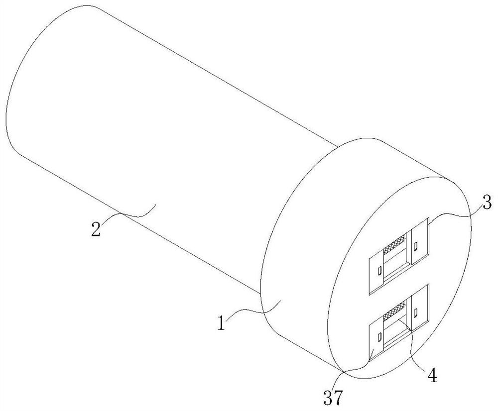
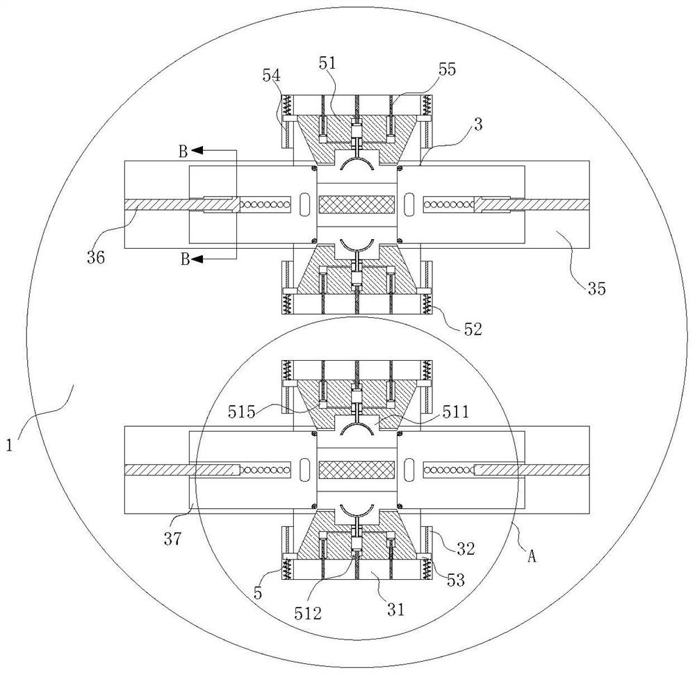
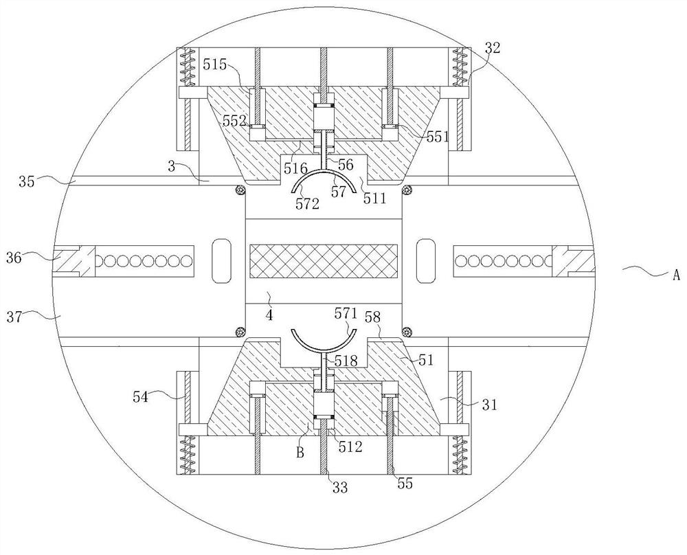
[0031] A multi-output USB charger such as Figure 1 to Figure 4 As shown, it includes a charging head 1, a casing 2, a connecting slot 3, a USB interface 4 and an anti-dropping mechanism. One side near the upper and lower ends is provided with a connection slot 3, the inside of the two groups of the connection slots 3 is provided with a USB interface 4, and the inside of the two groups of the connection slots 3 is provided with an anti-drop mechanism, and the anti-drop mechanism includes Two sets of anti-falling components 5, the inner surface of the connecting groove 3 is provided with movable grooves 31 at the upper and lower ends of the side away from the USB interface 4, and the anti-falling components 5 correspond to the movable grooves 31 one-to-one and are arranged in its interior ;
[0032] The anti-falling assembly 5 includes a movable plate 51, a first spring 52, a first sliding block 53, a first limit rod 54, a first fixed rod 55, a first movable rod 56 and an arc-shaped plate 57, and the movable plate 51 The movable plate 51 is slidably connected to the interior of the movable slot 31 , the outer surfaces of both sides of the movable plate 51 are fixedly connected with the first slider 53 on the side away from the connection slot 3 , and the inner surface of the movable slot 31 corresponds to the first slider 53 . The first sliding slot 32 is opened at the position of 1, and the first sliding block 53 is slidably connected to the inside of the first sliding slot 32, the first limit rod 54 is fixedly connected to the inside of the first sliding slot 32, and the first limit The position rod 54 is slidably connected with the first slider 53 , the first spring 52 is arranged at one end of the outer surface of the first position limit rod 54 away from the connecting groove 3 , and one end of the first spring 52 is fixedly connected with the first sliding groove 32 , and the other end is fixedly connected with the first slider 53;
[0033] A notch 511 is formed on the side of the outer surface of the movable plate 51 close to the connecting groove 3, and a first installation groove 512 is formed on the inner surface of the notch 511 near the middle. One end of the first movable rod 56 penetrates to the The inside of the first installation groove 512 is movably connected to it, the other end is fixedly connected to the arc-shaped plate 57 , the first connecting ring 513 is fixedly connected to one end of the outer surface of the first movable rod 56 inside the first installation groove 512 , and A first sealing sleeve 514 is fixed on the outer surface of the first connecting ring 513 , sealing cavities 515 are provided at the end of the outer surface of the movable plate 51 away from the connection groove 3 and close to both sides, and the inner surface of the movable groove 31 is far away from the connection. One end of the groove 3 and the position corresponding to the sealing cavity 515 are fixedly connected with the first fixing rod 55 , and one end of the outer surface of the first fixing rod 55 penetrates into the interior of the sealing cavity 515 and is fixedly connected with the first fixing block 551 . A second sealing sleeve 552 is fixedly connected to the outer surface of the first fixing block 551 , and the outer surface of the second sealing sleeve 552 is in close contact with the inner surface of the sealing cavity 515 , one side of the inner surface of the sealing cavity 515 is close to the bottom A connecting hole 516 is formed at the position of the end, and the connecting hole 516 extends to the inside of the first installation groove 512 , and the inside of the sealing cavity 515 is filled with compressed air with buffering effect.
[0034] When in use, the movable plate 51 is respectively displaced up and down relative to each other under the action of the first spring 52. At this time, the first fixed block 551 drives the second sealing sleeve 552 to move relatively in the sealing cavity 515. When the movable plate 51 is in balance with the force In the static state, the two groups of arc-shaped plates 57 corresponding to the inside of the connecting groove 3 are attached to each other to limit the connection line. The interior of the connecting hole 516 is airtight and the air pressure is in a balanced state, and at the same time, a pushing force is generated on the first movable rod 56, so the first fixing block 551, the second fixing block 34 and the first connecting ring 513 are relatively static, and due to the Both a fixed rod 55 and the second fixed rod 33 are fixedly connected to the movable slot 31, so when the connecting wire is accidentally touched or pulled to the outside and has a tendency to push the first movable rod 56, the movable plate 51 needs to be connected The direction of the slot 3 moves, and the movable plate 51 is restricted by the first spring 52 and it is difficult to move. In this process, the elastic force of the first spring 52 and the pushing force of the air pressure to the first movable rod 56 simultaneously act on the connecting line to carry out the movement. Restricted to prevent it from escaping from the interior of the connecting groove 3.
[0035] As an embodiment of the present invention, such as image 3 and Figure 4 As shown, a rubber block 571 is fixedly connected to the side of the outer surface of the arc-shaped plate 57 close to the connecting groove 3, and a buffer cavity 572 is formed between the rubber block 571 and the arc-shaped plate 57, and the interior of the buffer cavity 572 Filled with compressed air with buffering effect, one end of the first movable rod 56 close to the first connecting ring 513 penetrates to one side of the first connecting ring 513 and is fixedly connected with a second connecting ring 517. The second connecting ring 517 is connected. The outer surface of the ring 517 is also fixedly connected with the first sealing sleeve 514, and the outer surface of one side of the second connection ring 517 is provided with a through hole 518, and the inner surface of the through hole 518 communicates with the inner surface of the buffer cavity 572. The connecting hole 516 is located between the first connecting ring 513 and the second connecting ring 517 , the inner surface of the movable groove 31 is fixedly connected to the position corresponding to the first installation groove 512 with the second fixing rod 33 , and the second fixing rod 33 is One end penetrates into the inside of the first installation groove 512 and is fixedly connected with the second fixing block 34 , and the outer surface of the second fixing block 34 is also fixedly connected with a second sealing sleeve 552 .
[0036] During use, when the movable plate 51 is in a static state due to the force balance, a closed state is formed between the first connecting ring 513 and the second fixing block 34, and the air pressure is balanced. Therefore, when the rubber block 571 is squeezed by the outside world, the The air pressure balance between the connecting ring 513 and the second fixing block 34 and the elastic force of the first spring 52 cooperate with each other, which can enhance the buffering capacity of the anti-dropping component 5 while avoiding the rigid contact between the connecting wire and the arc plate 57 .
[0037] As an embodiment of the present invention, such as image 3 As shown, magnets 58 are provided on both sides of the outer surface of the movable plate 51 near one end of the connecting groove 3 .
[0038] During use, the two groups of movable plates 51 corresponding to the same group move toward the direction close to the connecting groove 3 under the action of the first spring 52 . 51 closely fit during use, and the direction of the adsorption force of the magnets 58 on the surface of the two sets of movable plates 51 is consistent with the direction of the corresponding elastic force of the first spring 52, thereby indirectly strengthening the buffering and anti-dropping ability of the device.
[0039] As an embodiment of the present invention, such as Figure 3 to Figure 6 As shown, both sides of the inner surface of the connection groove 3 are provided with second installation grooves 35, and the inner surface of the second installation groove 35 is fixedly connected to the limit plate 36 at one end away from the connection groove 3. The limit plate 36 A dustproof plate 37 is movably connected to the outer surface.
[0040] By arranging the dustproof plate 37, the connection slot 3 can be effectively closed when the charger is idle, thereby reducing the probability of dust entering the USB interface 4 through the connection slot 3 and affecting its normal use. The plate 37 is relatively moved to the left and right sides.
[0041] As an embodiment of the present invention, such as Figure 3 to Figure 6 As shown, one end of the limiting plate 36 penetrates into the interior of the dust-proof plate 37 and is movably connected thereto, and a limiting slot 371 is defined at the connection between the outer surface of the dust-proof plate 37 and the dust-proof plate 37, and the limiting slot 371 There are card slots 372 on both sides of the inner surface of the stopper plate 36 , and rotation slots 373 are formed on both sides of the outer surface of the limiting plate 36 corresponding to the card slots 372 . Block 375, and one side of the inner surface of the rotating groove 373 is provided with an arc-shaped elastic piece 374.
[0042] During use, the user pushes the dust-proof plate 37 to move relative to the left and right sides. During this process, the spherical blocking block 375 rotates inside the rotation groove 373. When the spherical blocking block 375 is misaligned with the blocking groove 372, the limiting groove 371 pushes the spherical clip 375 to squeeze the arc-shaped elastic piece 374 into the rotation slot 373. When the spherical clip 375 corresponds to the slot 372, the spherical clip 375 fits with the slot 372 under the action of the arc-shaped clip 374. , the stability of the dustproof plate 37 during use is effectively ensured by arranging the spherical blocking block 375 .
[0043] As an embodiment of the present invention, such as image 3 and Figure 5 As shown, the outer surface of the dust-proof plate 37 is provided with a groove on the side away from the limit plate 36, and the outer surface of the dust-proof plate 37 is away from the limit plate 36. For the roller 519 , the cross section of the movable plate 51 is trapezoidal, and the inclined surface of the movable plate 51 is in close contact with the outer surface of the roller 519 .
[0044] When in use, the user pushes the dust-proof plate 37 toward the direction close to the second installation groove 35 . At this time, the movable plate 51 is moved up and down relative to each other under the action of the first spring 52 , and the roller 519 rolls along the surface of the movable plate 51 . , to reduce the friction loss during the movement of the movable plate 51, and at the same time when the user finishes using, pull the dustproof plate 37 away from the second installation groove 35, and the roller 519 moves along the slope of the movable plate 51. , and push the movable plate 51 to move closer to the movable slot 31 until the two sets of dust-proof plates 37 inside the same set of connecting slots 3 are in close contact with each other.
[0045] Working principle: During use, the user holds the grooves on the surface of the dust-proof plate 37 and pushes the two sets of dust-proof plates 37 and makes them move relatively to the left and right sides. Internal rotation, when the spherical block 375 is misaligned with the groove 372, the limiting groove 371 pushes the spherical block 375 to squeeze the arc-shaped elastic piece 374 into the rotating groove 373. When the spherical block 375 corresponds to the groove 372 , the spherical block 375 is matched with the slot 372 under the action of the arc-shaped elastic piece 374, and during the movement of the dust-proof plate 37 to the inside of the second installation slot 35, the movable plate 51 is moved up and down respectively under the action of the first spring 52. relative displacement, and the roller 519 rolls along the surface of the movable plate 51, which reduces the friction loss generated by the movable plate 51 during the movement process. A fixed block 551 drives the second sealing sleeve 552 to move relatively inside the sealing cavity 515. When the movable plate 51 is in a static state with the force balance, the two sets of arc-shaped plates 57 corresponding to the inside of the connecting groove 3 are attached to each other. At the same time, when the movable plate 51 is in a static state due to the force balance, the sealed cavity 515 , the first installation groove 512 and the connecting hole 516 are sealed and the air pressure is in a balanced state, and at the same time, the first movable rod 56 is generated. , so the first fixing block 551 , the second fixing block 34 and the first connecting ring 513 are relatively stationary, and since the first fixing rod 55 and the second fixing rod 33 are both fixedly connected with the movable groove 31 , when the connecting line receives When it is accidentally touched or pulled to the outside and has a tendency to push the first movable rod 56, the movable plate 51 needs to move in a direction close to the connecting groove 3, and the movable plate 51 is restricted by the elastic force of the first spring 52. During the process, the elastic force of the first spring 52 and the pushing force of the air pressure to the first movable rod 56 simultaneously act on the connecting line to limit it, so as to prevent it from being separated from the interior of the connecting groove 3. Similarly, it can be seen that when the movable plate 51 is balanced by force In the static state, the first connecting ring 513 and the second fixing block 34 form a closed state, and the air pressure is balanced. Therefore, when the rubber block 571 is squeezed by the outside world, the space between the first connecting ring 513 and the second fixing block 34 is used. The air pressure balance of 1 and the elastic force of the first spring 52 cooperate with each other, which can strengthen the buffering capacity of the anti-fall component 5 while avoiding the rigid contact between the connecting wire and the arc-shaped plate 57 .
[0046]Although embodiments of the present invention have been shown and described, it will be understood by those skilled in the art that various changes, modifications, and substitutions can be made in these embodiments without departing from the principle and spirit of the invention and modifications, the scope of the present invention is defined by the appended claims and their equivalents.