Cleaning device, scrubber and sweeper

A cleaning device and host technology, applied in the direction of carpet cleaning, floor cleaning, cleaning machinery, etc., can solve the problems of leaving traces and reducing the working efficiency of the host, and achieve the effect of good floor cleaning.

Pending Publication Date: 2021-11-16
NINGBO FUJIA IND
View PDF2 Cites 0 Cited by
  • Summary
  • Abstract
  • Description
  • Claims
  • Application Information

AI Technical Summary

Problems solved by technology

However, after the rag mopping the floor becomes dirty, it still cannot be cleaned in time. If the dirty...

Method used


Image

  • Cleaning device, scrubber and sweeper
  • Cleaning device, scrubber and sweeper
  • Cleaning device, scrubber and sweeper

Examples


Embodiment 1

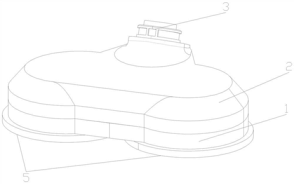
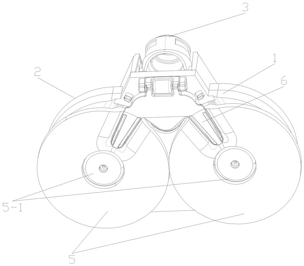
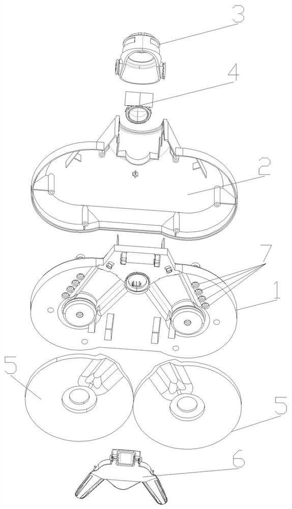
[0034] Such as Figures 1 to 4 As shown in , the cleaning device of the present invention includes a bracket 1, a motor 8 is arranged on the upper side of the bracket 1, and a transmission assembly 9 is arranged on the left and right sides of the motor 8, and the output shaft of the motor 8 is driven by the two left and right transmission assemblies 9. connection, the transmission assembly 9 adopts a worm gear transmission assembly, and an outer cover 2 is also arranged on the bracket 1, and the outer cover 2 is used to cover and protect the structure on the bracket 1; two circular rags 5 are arranged on the lower side of the bracket 1, The centers of the two rags 5 are provided with connecting parts, and the connecting parts are clamping parts 5-1, and the clamping parts 5-1 are clamped on the upper and lower sides of the center of the rags 5, so that the rags 5 are fixed, and the rags 5 The other parts of the other parts do not overlap with the clamping part 5-1, and the two...

Embodiment 2

[0038] The difference between the cleaning device in this embodiment and Embodiment 1 is that the rag rotates in a crawler type, and the position where the working surface 6-1 of the scraper 6 collides with the rag and the position where the water spray port 7 wets the rag are respectively located on the mopping surface of the rag. The two ends of the working surface, the mopping working surface of the rag refers to the plane in contact with the ground on the rag, when the cleaning device in this embodiment works, any point on the rag 5 is wetted by the water spray port 7 at one end of the mopping working surface , and then gradually become dirty during the mopping process. When it moves to the other end of the mopping surface, it is scraped off by the working surface 6-1 of the scraper and squeezed out the sewage, and then leaves the mopping surface, and so on. , to ensure that the rag can be cleaned in time before leaving the ground, and the sewage and solid dirt on the rag w...

Embodiment 3

[0040] The difference between the cleaning device in this embodiment and Embodiment 1 is that the rag moves reciprocatingly relative to the scraper, and the position where the water jet 7 wets the rag is on both sides of the position where the working surface 6-1 of the scraper 6 collides with the rag. , when the cleaning device in the present embodiment works, any point on the rag 5 is scraped off by the working surface 6-1 of the scraper 6 after mopping the floor and squeezed out the sewage, and then immediately wetted by the water spray port 7, After the rag is cleaned, it can better mop the ground, and then the point is cleaned by the scraper during the reverse movement. This cycle ensures that the rag can be cleaned in time, and the sewage and solid dirt on the rag will not fall on the ground. If any point on the rag can be wetted before being squeezed by the scraper, it will help to wash away the dirt on the rag and dilute the sewage on the rag, making the rag easier to ...


PUM


Abstract

The invention relates to a cleaning device, a scrubber and a sweeper. The cleaning device comprises a support, cleaning cloth, a scraper and a structure used for wetting the cleaning cloth, the support is used for supporting the cleaning cloth and the scraper, the working face of the scraper is arranged below the cleaning cloth and abuts against the cleaning cloth, the working face of the scraper is further provided with a suction port, the cleaning cloth is used for mopping the floor, the cleaning cloth can move relative to the scraper, the working face of the scraper is used for scraping the cleaning cloth and squeezing sewage on the cleaning cloth when the scraper and the cleaning cloth move relative to each other, the squeezed sewage and the scraped dirt fall into the suction port, and a sewage channel communicated with the suction port is further formed in the scraper. After the cleaning cloth is wetted, the ground can be mopped in a wet mode, after the cleaning cloth becomes dirty, dirt on the cleaning cloth can be scraped off through the scraper, sewage on the cleaning cloth is squeezed, the cleaning cloth can be cleaned in time, the sewage and the dirt fall into the suction port and can be treated in time through the sewage channel, no trace is left on the ground, and the ground cleaning effect is good.

Description

technical field [0001] The invention relates to the technical field of automatic cleaning, and more specifically relates to a cleaning device, a floor washing machine and a floor sweeping machine. Background technique [0002] At present, the bottoms of automatic cleaning equipment such as washing machines, mopping machines, mopping machines and some sweepers on the market are equipped with rags. The rags are used for wet mopping the ground. Afterwards, it will become dirty and cannot be cleaned in time. With the operation of the automatic equipment, the dirty rag will continue to wet the ground, and the dust on the rag will remain on the ground with the sewage, leaving traces on the ground, and the ground is still dirty. , the cleaning effect is not good. [0003] In order to solve the problem of dirty rags, some research has been done in the industry: [0004] Such as some crawler-type rags, as described in Chinese patent CN201510054983.1, the rag is crawler-type in the ...

Claims


Application Information

Patent Timeline
IPC IPC(8): A47L11/293A47L11/40
CPCA47L11/293A47L11/40A47L11/4016A47L11/4038A47L11/4083A47L11/4088A47L11/4094
Inventor 方剑强郑建明王胜林
Owner NINGBO FUJIA IND
Why Eureka
Try Eureka