Automatic jacking and breaking mechanism for casting part

A casting and jacking technology, which is applied in the configuration of casting equipment, manufacturing tools, indicating equipment/measuring equipment, etc., can solve the problems of manpower consumption, inconvenient handling, heavy weight, etc., to prevent invalid continuous pushing and solve the problem of manpower Harsh environment, the effect of realizing safe automatic jacking off work

Pending Publication Date: 2021-11-16
昆山竹科机电有限公司
View PDF0 Cites 0 Cited by
  • Summary
  • Abstract
  • Description
  • Claims
  • Application Information

AI Technical Summary

Problems solved by technology

[0002] The principle of lost foam casting is to use meltable plastic or foam to fix the mold base, and then fix the mold frame by shaping sand, etc., and pour the molten metal water of the casting into the interior. Due to the high temperature, the plastic or the mold is burned, and the casting There are multiple castings in one mold, but they are all connected as a whole during casting, that is to say, there is a "welding" between the casting and the mold base as a whole, that is, the gate needs to be broken, in other words, it is casting The pieces need to be knocked off the formwork one by one
[0003] For a mold base, hundreds of products can be molded at one time. Due to the metal structure, the weight is heavy and it is extremely inconvenient to carry
In most cases, after casting, the workers break the casting from the gate of the mold base by external force knocking. Knocking off the gate and breaking it will lead to high labor intensity, high noise, low efficiency, and even unsatisfactory fracture, resulting in low pass rate

Method used


Image

  • Automatic jacking and breaking mechanism for casting part
  • Automatic jacking and breaking mechanism for casting part
  • Automatic jacking and breaking mechanism for casting part

Examples


Embodiment Construction

[0043] The specific implementation manners of the present invention will be further described in detail below in conjunction with the accompanying drawings and embodiments. The following examples are used to illustrate the present invention, but are not intended to limit the scope of the present invention.

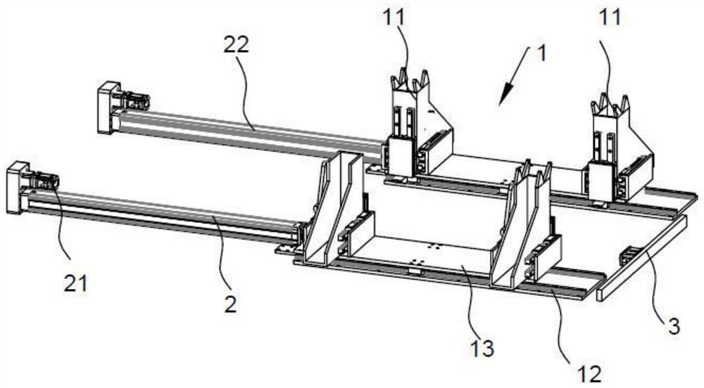
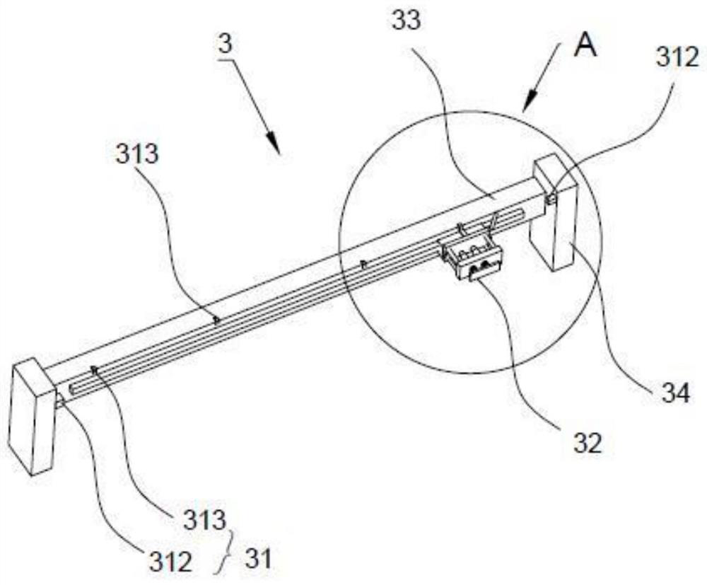
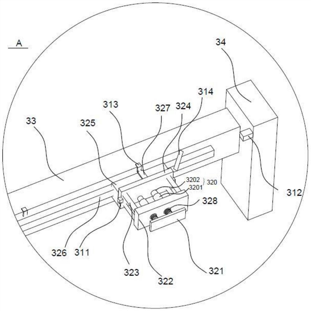
[0044] An automatic lifting mechanism for castings, including a loading structure 1, which is located on the first track 12 below the feeding track, and is used to place and fix casting racks conveyed from the feeding track; a lifting power structure 2 , the structure is located behind the loading structure, connected with the loading machine structure 1, used to drive the loading knot mechanism to slide on the first track 12; the top tightening structure 3, the structure is located in front of the loading structure 3, including the induction system 31 And tighten the slider 32, the induction system 31 is used for positioning and monitoring materials;

[0045] When the in...


PUM


Abstract

The invention relates to an automatic jacking and breaking mechanism for a casting part. The automatic jacking and breaking mechanism comprises a carrying structure, a jacking and breaking power structure and a jacking and tightening structure, wherein the carrying structure is located on a first track below a conveying track and used for storing and fixing a casting part frame conveyed from the conveying track; the jacking and breaking power structure is located behind the carrying structure, fixed to the first track, connected with the carrying structure and used for driving the carrying structure to slide on the first track; the jacking and tightening structure is located in front of the carrying structure and comprises a sensing system and a jacking and tightening sliding block, and the sensing system is used for positioning and monitoring materials; and when the sensing system monitors the casting part, the jacking and tightening sliding block jacks and tightens the casting part, and the jacking and breaking power structure pushes the carrying structure to slide on the first track towards one end of the jacking and tightening structure so that the casting part can be jacked and broken from the frame. By arrangement of the carrying structure, the jacking and breaking power structure and the jacking and tightening structure, efficient, safe and automatic jacking and breaking work of the large casting part is achieved, and the problems that the manpower environment is severe, the amount of dust is large, and the efficiency is low are solved.

Description

technical field [0001] The invention relates to an automatic jacking mechanism for castings, which belongs to the field of mechanical automation. Background technique [0002] The principle of lost foam casting is to use meltable plastic or foam to fix the mold base, and then fix the mold frame by shaping sand, etc., and pour the molten metal water of the casting into the interior. Due to the high temperature, the plastic or the mold is burned, and the casting There are multiple castings in one mold, but they are all connected as a whole during casting, that is to say, there is a "welding" between the casting and the mold base as a whole, that is, the gate needs to be broken, in other words, it is casting The pieces need to be knocked off the formwork one by one. [0003] For a mold base, hundreds of products can be molded at one time. Due to the metal structure, the weight is heavy and it is extremely inconvenient to carry. In most cases, after casting, the workers break ...

Claims


Application Information

Patent Timeline
Patent Type & Authority Applications(China)
IPC IPC(8): B22D31/00B22D2/00
CPCB22D31/00B22D2/00
Inventor 余黎明
Owner 昆山竹科机电有限公司
Why Eureka
Try Eureka