Annular light spot optical system for metal SLM printing and printing method

A ring-shaped spot and optical system technology, applied in the field of ring-shaped spot optical system, can solve the problems of rapid heating and cooling, affecting the performance of finished products, excessive energy concentration, etc., to achieve better printing effect contrast, ensure mechanical properties, and avoid defects.

Active Publication Date: 2021-11-16
GUANGXI UNIV
View PDF8 Cites 5 Cited by
  • Summary
  • Abstract
  • Description
  • Claims
  • Application Information

AI Technical Summary

Problems solved by technology

At present, most of the SLM processing equipment use the traditional Gaussian density distribution laser beam (single-mode TEM00 mode). Since the energy of the central position of Gaussian light is high, while the energy of the edge position is low, it is often caused by uneven energy distribution during processing. Cause defects such as pores
In view of the special energy distribution of Gaussian light, increasing the laser power will cause excessive concentration of energy, resulting in remelting, keyhole and other problems
Reduce remelting and keyholes by increasing the scanning speed, but the increase in scanning speed will cause rapid heating and rapid cooling in the processing process
During rapid cooling, the appearance of some unstable intermediate phases (such as: low melting point eutectic structure and compounds) will make the structure more uneven and affect the performance of the finished product

Method used


Image

  • Annular light spot optical system for metal SLM printing and printing method
  • Annular light spot optical system for metal SLM printing and printing method
  • Annular light spot optical system for metal SLM printing and printing method

Examples


Embodiment Construction

[0029] The present invention will be described in further detail below in conjunction with the accompanying drawings and specific embodiments. It should be noted that the specific embodiments and accompanying drawings are not intended to limit the scope of rights of the present invention.

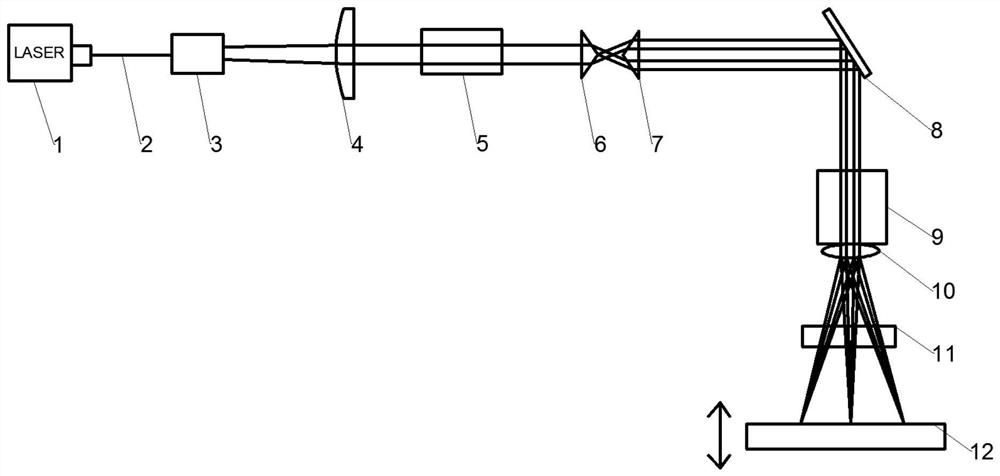
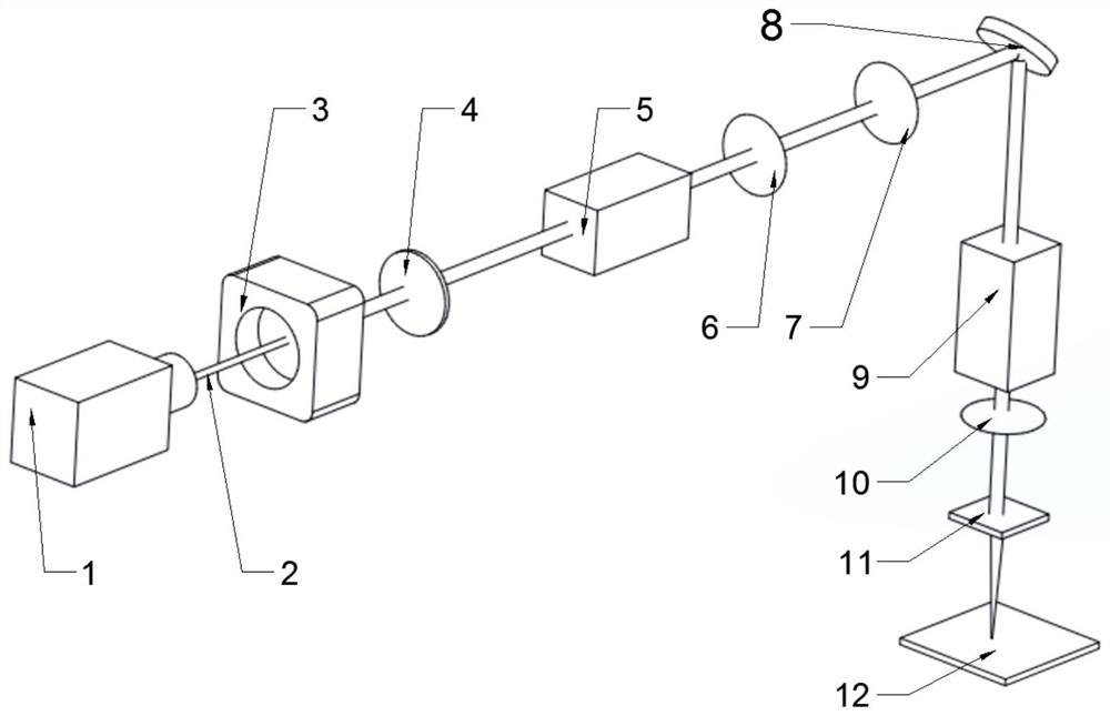
[0030] Such as Figure 1 to Figure 6As shown, the annular spot optical system for metal SLM printing in this specific embodiment includes a laser 1, a collimator 4, a variable magnification beam expander 5, A beam shaping unit, a total reflection mirror 8 , a galvanometer system 9 , a field mirror 10 , a beam quality analyzer 11 and a working platform 12 .

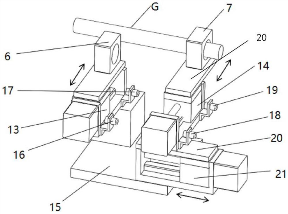
[0031] The beam shaping unit of this specific embodiment is set in the metal SLM printer, and the overall optimization of the processing method of the parts is carried out in cooperation with the path planning of the printer equipment. The beam shaping unit includes a first conical lens 6, a second conical lens 7 and an electric switch...


PUM


Abstract

The invention discloses an annular light spot optical system for metal SLM printing and a printing method. The annular light spot optical system comprises a laser device, and the laser device is connected with a collimator through an optical fiber; a Gaussian beam emitted by the laser device is collimated through the collimator, and the size of a light spot of the collimated Gaussian beam is adjusted through a variable-magnification beam expander; a light beam shaping unit comprises a first conical lens and a second conical lens; and the Gaussian beam with the light spot size adjusted sequentially passes through the first conical lens and the second conical lens to be shaped, and the shaped beam sequentially passes through a total reflection mirror, a galvanometer system and a field lens to form a focused light spot to reach a working platform. According to the annular light spot optical system, the Gaussian light spot, an annular light spot or an elliptical light spot can be independently used for printing, and light paths can be freely switched for printing in different stages of the printing process, so that the printing efficiency and quality can be improved, the defects of metal printing can be reduced, and the application of the SLM technology can be promoted.

Description

technical field [0001] The invention relates to the field of optical fiber laser beam shaping, in particular to an annular spot optical system for metal SLM printing and a printing method thereof. Background technique [0002] As a kind of additive manufacturing technology (AM), selective laser melting technology (SLM) can process parts with complex structures, and its finished products have high forming precision, and are widely used in medical, aerospace and other fields. At present, most of the SLM processing equipment use the traditional Gaussian density distribution laser beam (single-mode TEM00 mode). Since the energy of the central position of Gaussian light is high, while the energy of the edge position is low, it is often caused by uneven energy distribution during processing. Cause defects such as pores. In view of the special energy distribution of Gaussian light, increasing the laser power will cause excessive concentration of energy, resulting in remelting, key...

Claims


Application Information

Patent Timeline
Patent Type & Authority Applications(China)
IPC IPC(8): B22F10/28B22F10/366B22F12/41B22F12/44B33Y30/00
CPCB22F10/28B22F10/366B22F12/41B22F12/44B33Y30/00Y02P10/25
Inventor 龙雨纪昌豪郭兴张晶周莉丽谢文明劳善源
Owner GUANGXI UNIV
Why Eureka
Try Eureka