Beam shaping system for metal SLM printing

A beam shaping, metal technology, applied in the direction of optics, optical components, process efficiency improvement, etc., can solve problems such as not being well elucidated

Active Publication Date: 2020-10-20
GUANGXI UNIV
View PDF10 Cites 10 Cited by
  • Summary
  • Abstract
  • Description
  • Claims
  • Application Information

AI Technical Summary

Problems solved by technology

SLM is a multi-factor coupling effect of laser, material and processing atmosphere. The mec

Method used


Image

  • Beam shaping system for metal SLM printing
  • Beam shaping system for metal SLM printing
  • Beam shaping system for metal SLM printing

Examples


Embodiment Construction

[0023] The present invention will be described in further detail below in conjunction with the accompanying drawings and specific embodiments. It should be noted that the specific embodiments and accompanying drawings are not intended to limit the scope of rights of the present invention.

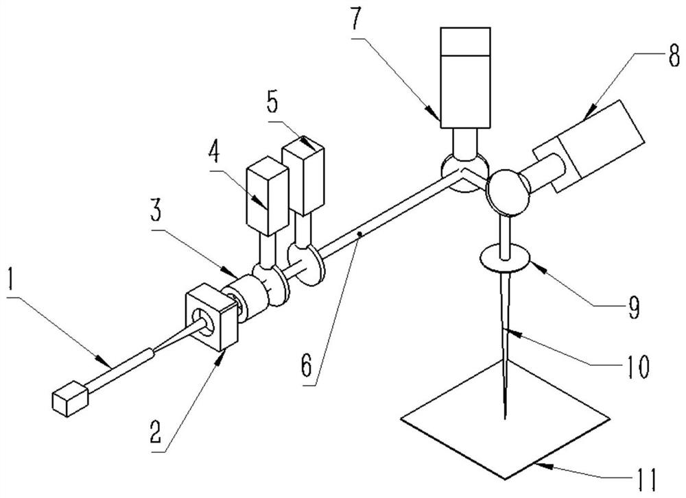
[0024] Such as Figure 1 to Figure 6 As shown, this embodiment provides a beam shaping system for metal SLM printing, including a laser 1, a collimator 2 arranged in sequence along the propagation direction of the laser beam emitted by the laser 1, a variable magnification beam expander 3, and a beam Shaping mechanism, galvanometer system and working platform 11, laser 1 is connected to collimator 2 with fiber interface through optical fiber, collimator 2 is connected to variable magnification beam expander 3, and variable magnification beam expander 3 is connected to beam shaping mechanism , the laser beam emitted by the laser 1 is collimated by the collimator 2, and the collimated beam em...


PUM


Abstract

The invention provides a light beam shaping system for metal SLM printing. The system comprises a laser, and a collimator, a zoom beam expander, a beam shaping mechanism, a galvanometer system and a working platform which are sequentially arranged in the propagation direction of laser beams emitted by the laser. A laser beam emitted by the laser is transmitted through an optical fiber to the collimator with an optical fiber interface for collimation, and the spot size is adjusted through the zoom beam expander to meet the incident spot size requirement of the beam shaping mechanism, the incident spots are shaped through a beam homogenizer or a beam shaper and then converted into flat-topped spots, the flat-topped spots are focused through the galvanometer system to form gathered spots, andthen the gathered spots reach the working surface to machine the metal powder. According to the system, light beam energy is redistributed to obtain circular, rectangular and oval flat-topped light spots or flat-topped light spots of specific shapes are customized according to requirements, metal printing defects can be effectively reduced through shaping of the system, and meanwhile, efficient printing can be conducted by introducing a high-power laser system in cooperation with large-size light spots.

Description

technical field [0001] The invention relates to the field of optical fiber laser beam shaping, in particular to a beam shaping system for metal SLM printing. Background technique [0002] my country has made remarkable achievements in the research of laser selective melting (SLM), one of the main technologies of 3D printing, and it has been widely used. However, problems such as printing quality, printing efficiency, and repeatable consistency still restrict the application of powder-spreading SLM technology. Defects (porosity, cracks, incompletely fused particles, etc.), deformation, and anisotropy of structural properties during the printing process are still prominent, making metal 3D printing impossible to implement in fatigue life-related application scenarios. Common methods to improve printing quality mainly include optimizing process parameters and paths, optimizing inert gas flow field, and improving powder quality, etc. SLM is a coupling effect of multiple factor...

Claims


Application Information

Patent Timeline
IPC IPC(8): G02B27/09B22F3/105B33Y30/00
CPCG02B27/0905G02B27/0927G02B27/0933B33Y30/00Y02P10/25
Inventor 龙雨王方
Owner GUANGXI UNIV
Why Eureka
Try Eureka