Manufacturing process of wind turbine blade

A wind turbine blade and manufacturing process technology, which is applied to other household appliances, household appliances, household components, etc., can solve problems such as glue accumulation, long production time, and affecting the quality of wind turbine blades

Pending Publication Date: 2021-11-16
无锡风电设计研究院有限公司
View PDF3 Cites 0 Cited by
  • Summary
  • Abstract
  • Description
  • Claims
  • Application Information

AI Technical Summary

Problems solved by technology

However, the manufacturing process of the existing wind turbine blades is to prefabricate the main girder, web, and small web respectively, and then lay the prefabricated main girder structure in the shell layer, and lay up dozens of layers of trailing edge beam sheets at the same time. For the fiber cloth, wait for the shell part to solidify and form, and then paste the web and small web respectively inside the blade shell. Therefore, the entire production cycle of the wind turbine blade needs to produce the main girder before the shell can be laid. , so that the production time is long; dozens of layers of trailing edge beam unidirectional fabric layups are prone to problems such as positioning errors and layup folds during the production process, which reduces the safety factor of the blade structure; For beams and webs, first place the main beams into the blade shell layup for vacuum infusion, and then connect the webs and shells by bonding, the installation steps are cumbersome
In addition, in actual manufacturing, the main girder is a prefabricated laminate. The prefabricated laminate cannot penetrate the resin, and the resin can only flow downward from the side. The impervious problem of perfusion below affects the quality of wind turbine blades

Method used


Image

  • Manufacturing process of wind turbine blade
  • Manufacturing process of wind turbine blade
  • Manufacturing process of wind turbine blade

Examples


Embodiment Construction

[0036] The present invention is described in further detail now in conjunction with accompanying drawing. These drawings are all simplified schematic diagrams, which only illustrate the basic structure of the present invention in a schematic manner, so they only show the configurations related to the present invention.

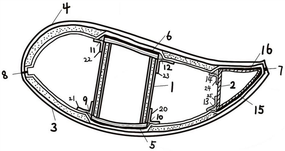
[0037] A manufacturing process of a wind turbine blade, comprising the following steps:

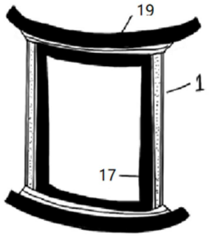
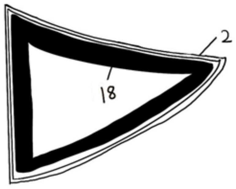
[0038] S1: Design the box-shaped main girder web mold 17, the small web trailing edge beam mold 18 and the blade shell mold according to the structure of the wind turbine blade;

[0039] S2: Make box-shaped main girder web 1, small web trailing edge beam 2 and blade shell respectively in box-type main girder web mold 17, small web trailing edge beam mold 18 and blade shell mould;

[0040] S3: Install the box-shaped main girder web 1 and the small web trailing edge girder 2 in the blade shell.

[0041] The blade shell in this embodiment includes a SS surface shell 3 and ...


PUM


Abstract

The invention relates to the technical field of wind turbine blade manufacturing, and discloses a manufacturing process of a wind turbine blade. The manufacturing process of the wind turbine blade comprises the following steps of S1, designing a box type main beam web mold, a small web trailing edge beam mold and a blade shell mold according to the structure of the wind turbine blade; S2, manufacturing a box type main beam web, a small web trailing edge beam and a blade shell in the box type main beam web mold, the small web trailing edge beam mold and the blade shell mold correspondingly; and S3, installing the box type main beam web and the small web trailing edge beam in the blade shell. In the actual use process, the box type main beam web, the small web trailing edge beam and the blade shell are firstly prefabricated in a component-by-component mode and then are formed in a bonding mode, so that the production efficiency of the wind turbine blade is greatly improved.

Description

technical field [0001] The invention relates to the technical field of manufacturing wind turbine blades, in particular to a manufacturing process for wind turbine blades. Background technique [0002] With the gradual consumption of non-renewable resources and in order to reduce the pollution caused by the consumption of non-renewable resources, new energy sources such as solar energy, wind energy and water energy are continuously applied in people's daily life to reduce the consumption of non-renewable resources. Our country has a vast territory, many areas have high altitudes, many mountainous areas, and abundant wind power, which is suitable for wind turbines to convert wind energy into electricity. [0003] In the wind turbine, the wind turbine blade is used as a wind energy conversion device to convert the wind energy into the kinetic energy of the generator. Its good performance is the decisive factor to ensure the normal and stable operation of the wind turbine. How...

Claims


Application Information

Patent Timeline
IPC IPC(8): B29C70/36B29C70/54B29L31/08
CPCB29C70/36B29C70/54B29L2031/085Y02E10/72Y02P70/50
Inventor 叶婷婷李丹陈程徐杰包洪兵俞志强管彩文
Owner 无锡风电设计研究院有限公司
Why Eureka
Try Eureka