Packaging structure of electrical equipment

A technology of electrical equipment and packaging structure, applied in the field of packaging structure of electrical equipment, can solve the problems of twisting and deformation of connecting rods, inability to balance the force of connecting rods, damage of connecting parts, etc.

Pending Publication Date: 2021-11-16
GREE ELECTRIC APPLIANCES INC OF ZHUHAI
View PDF0 Cites 0 Cited by
  • Summary
  • Abstract
  • Description
  • Claims
  • Application Information

AI Technical Summary

Problems solved by technology

The existing "I"-shaped packaging foam cannot balance the force on the connecting rod, nose and tail, which may cause the conn

Method used


Image

  • Packaging structure of electrical equipment
  • Packaging structure of electrical equipment
  • Packaging structure of electrical equipment

Examples


Example Embodiment

[0040] The technical solutions of the present invention will be clearly and completely described below with reference to the accompanying drawings. Obviously, the described embodiments are a part of the embodiments of the present invention, but not all of the embodiments. Based on the embodiments of the present invention, all other embodiments obtained by those of ordinary skill in the art without creative efforts shall fall within the protection scope of the present invention.

[0041]In the description of the present invention, it should be noted that the terms "center", "upper", "lower", "left", "right", "vertical", "horizontal", "inner", "outer", etc. The indicated orientation or positional relationship is based on the orientation or positional relationship shown in the accompanying drawings, which is only for the convenience of describing the present invention and simplifying the description, rather than indicating or implying that the indicated device or element must have...


PUM


Abstract

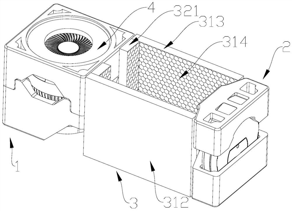
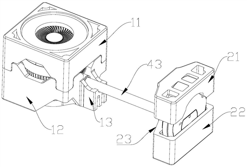
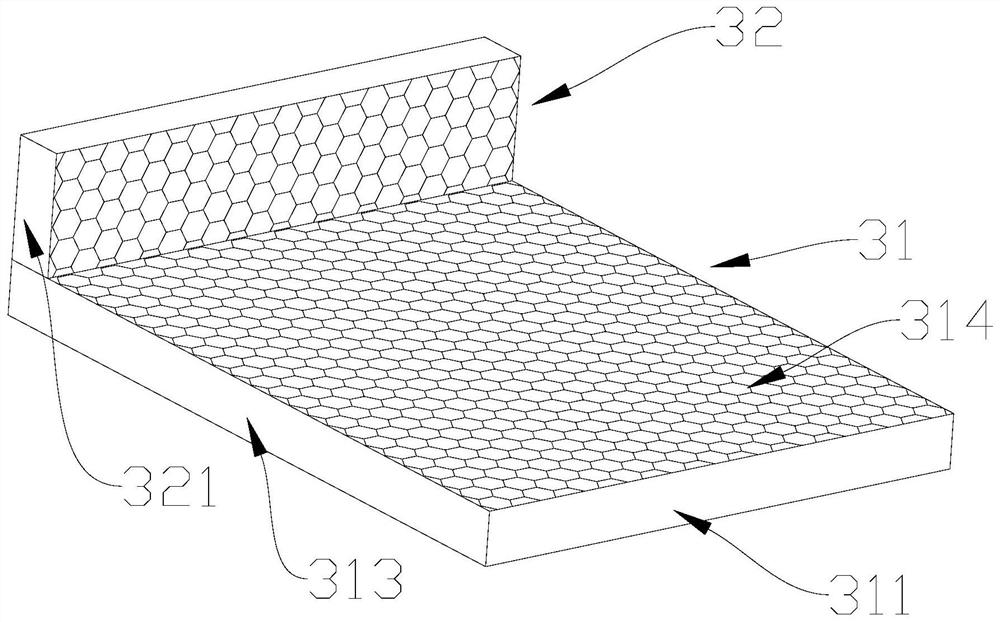
The invention relates to the technical field of packaging structures, in particular to a packaging structure of electrical equipment. The electrical equipment comprises a machine head, a machine tail and a connecting rod connecting the machine head and the machine tail, the packaging structure of the electrical equipment comprises a first packaging assembly, a second packaging assembly and a supporting assembly, and the first packaging assembly is suitable for packaging the machine head; and the second packaging assembly is suitable for packaging the machine tail. The supporting assembly comprises at least two supporting plates which are oppositely arranged and located at the two sides of the connecting rod, and the two ends of the supporting plates abut against the first packaging assembly and the second packaging assembly correspondingly. According to the packaging structure of the electrical equipment, the supporting plates slow down the opposite displacement trend of the connecting rod and the machine tail, and the stress of the connecting rod, the stress of the machine head and the stress of the machine tail are balanced.

Description

technical field [0001] The invention relates to the technical field of packaging structures, in particular to a packaging structure for electrical equipment. Background technique [0002] Some current electrical equipments with inseparable fuselages, such as electric fans, generally include a nose, a tail and a connecting rod connected between the nose and the tail, and the weight of the nose and the tail is relatively heavy. Due to the functional requirements of the product, the overall dimensions of the nose and tail are generally larger, while the outer dimensions of the middle connecting rod are smaller, in the shape of the English letter "I". For this type of product, the conventional packaging method in the industry is to lay the whole machine flat, and wrap it with two pieces of packaging foam that are in the shape of the fuselage to form an "I"-shaped packaging foam that is in the shape of the fuselage. The packing box is packed, and the outer surface of the packing...

Claims


Application Information

Patent Timeline
IPC IPC(8): B65D81/113B65D81/05B65D85/68
CPCB65D81/113B65D81/05B65D85/68
Inventor 卢思翰谢培青赵岚
Owner GREE ELECTRIC APPLIANCES INC OF ZHUHAI
Why Eureka
Try Eureka