Sweeping roller and belt conveyor

A belt conveyor and cleaning roller technology, which is applied to conveyor objects, cleaning devices, transportation and packaging, etc., can solve problems such as poor cleaning effect, improve cleaning effect, improve dust situation, and reduce re-adhesion. The effect of the odds on the conveyor belt

Active Publication Date: 2021-11-16
ZHENGZHOU TONGDING MASCH EQUIP CO LTD
View PDF8 Cites 1 Cited by
  • Summary
  • Abstract
  • Description
  • Claims
  • Application Information

AI Technical Summary

Problems solved by technology

[0004] The purpose of the present invention is to provide a cleaning roller to solve the technical problem in the prior art tha...

Method used


Image

  • Sweeping roller and belt conveyor
  • Sweeping roller and belt conveyor
  • Sweeping roller and belt conveyor

Examples


specific Embodiment 1

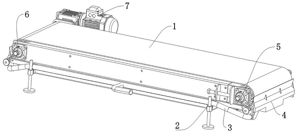
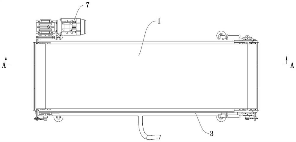
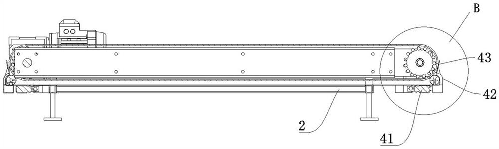
[0052] like Figure 1 to Figure 6 As shown, the belt conveyor in this embodiment can be used for conveying valve pockets. Corresponding to the conveying belt 1, a cleaning powder collecting device is configured to clean the dust on the conveying belt 1. The cleaning roller 10 of the cleaning powder collecting device is not only provided with There is a brush 102 and a single-rotation spiral conveying blade 103. In this way, the surface of the conveying belt 1 is swept by the brush 102, and the brushed dust is conveyed by the spiral conveying blade 103 to the dust collector of the cleaning roller 10. In this way, the dust that has been swept is transported in one direction by the screw conveying blade 103 in a centralized manner, and will not be scattered everywhere, which effectively improves the dust collection efficiency.

[0053] like Figure 1 to Figure 6 As shown, the belt conveyor in this embodiment includes a conveyor frame body 2, the conveyor frame body 2 extends in ...

specific Embodiment 2

[0065] The main difference between it and Example 1 is that: in Example 1, the rotation direction of the cleaning roller is opposite to the rotation direction of the conveying belt, and the cleaning can be reversed to improve the cleaning effect. In this embodiment, the rotation direction of the cleaning roller can also be consistent with the rotation direction of the conveying belt.

specific Embodiment 3

[0067] The main difference from Example 1 is that in Example 1, when the corresponding belt roller drives the cleaning roller to rotate through the belt drive mechanism, a figure-eight belt is used, so that the rotation direction of the cleaning roller is opposite to the rotation direction of the conveying belt. In this implementation, a motor can be separately configured for each cleaning roller, and the cleaning roller is directly driven by the motor to rotate in the forward direction or in the reverse direction.


PUM


Abstract

The invention relates to a sweeping roller and a belt conveyor. The sweeping roller comprises a roller shaft, wherein brushes are distributed on the peripheral surface of the roller shaft, the brushes extend in the radial direction of the roller shaft, and the brushes are used for being driven by the roller shaft to rotate so as to sweep a conveying belt; and spiral conveying blades are further arranged on the peripheral surface of the roller shaft, the axial direction of the spiral conveying blades extends in the left-right direction, the spiral conveying blades with the single rotating direction form a one-way through spiral conveying channel on the outer side of the roller shaft, the spiral conveying channel is used for conveying dust swept by the brushes to the dust collecting end of the sweeping roller in a one-way mode, and the brushes are located in the spiral conveying channel. The brushes are arranged on the peripheral surface of the roller shaft, and the spiral conveying blades are further arranged on the peripheral surface of the roller shaft, so that when the sweeping roller rotates, the brushes can be used for brushing and sweeping the surface of the conveying belt, the spiral conveying blades are further used for conveying the brushed and swept dust to the dust collecting end of the sweeping roller, the probability that the dust is adhered to the conveying belt again is reduced, and the sweeping effect can be effectively improved.

Description

technical field [0001] The invention relates to a cleaning roller and a belt conveyor. Background technique [0002] In the valve bag feeder in the dry powder mortar industry on the market, during the powder filling process, since the valve bag is withdrawn from the powder filling pipe, the bag body falls to the conveyor belt, and the bag mouth is closed and arranged on the conveyor belt. Falling or disturbing of the bag body can cause dust to fall off from the valve pocket, and most of the dust that falls off will fall to the conveyor belt. As the conveyor belt rotates and conveys, the dust falling off the conveyor belt will cause dust to appear on the work site, and it will always adhere to the conveyor belt. Dust on the conveyor belt can also affect the rotation of the conveyor belt. [0003] For the dust on the conveyor belt, the most commonly used method is the combination of roller brushing and purging. For example, the conveyor belt dust removal device disclosed in t...

Claims


Application Information

Patent Timeline
IPC IPC(8): B65G45/18B65G45/26
CPCB65G45/18B65G45/26
Inventor 董青山毛君豪丁岩刘广磊赵文龙
Owner ZHENGZHOU TONGDING MASCH EQUIP CO LTD
Why Eureka
Try Eureka