Installation method of small-gap soft-tooth steam seal

An installation method and small gap technology, which can be applied in the direction of safety devices, leakage prevention, engine components, etc., can solve the problems of affecting the efficiency of the high and medium pressure cylinders of the steam turbine, increasing the leakage loss of the high and medium pressure cylinders of the steam turbine, and increasing the leakage loss, etc. , to achieve obvious energy saving effect, reduce steam leakage loss and improve internal efficiency

Pending Publication Date: 2021-11-16
陕煤电力信阳有限公司
View PDF5 Cites 0 Cited by
  • Summary
  • Abstract
  • Description
  • Claims
  • Application Information

AI Technical Summary

Problems solved by technology

However, in order to save costs, the high, medium and low pressure cylinders are all connected by a single shaft. The material originally designed and installed by the manufacturer of the blade top seal of the steam turbine's high, medium and high pressure cylinders is relatively hard. When the vibration of the unit increases during operation, it will cause friction and wear to the high and medium pressure rotor shrouds. The material of the blade top seal is relatively hard, resulting in obvious wear and tear grooves on the outer surface of the high and medium pressure rotor shrouds of the steam turbine, resulting in increased steam leakage losses between the stages of the high and medium pressure cylinders of the steam turbine, seriously affecting the internal efficiency of the high and medium pressure cylinders of the steam turbine, and further affecting Power supply coal consumption of the whole unit
After the unit has been in operation for several years, there are obvious wear grooves on the shroud belt of the high and medium pressure rotor of the steam turbine, and the deepest part is nearly 1mm deep, resulting in increased leakage loss between the stages of the high and medium pressure cylinders of the steam turbine, seriously affecting the internal efficiency of the high and medium pressure cylinders of the steam turbine. This in turn affects the power supply coal consumption of the entire unit. However, there are still various problems in various high and medium pressure cylinders on the market.
[0003] As the authorized announcement number is CN103953401B disclosed thermal power plant steam turbine high and medium pressure cylinder, although it has realized a simple structure, does not need to change the structure of the original equipment, utilizes the cylinder hole on the high and medium pressure outer cylinder, seals the high and medium pressure cylinder shaft Steam is introduced into the interlayer cavity of the high and medium pressure cylinder to heat the outer wall of the high and medium pressure inner cylinder, thereby reducing the temperature difference between the inside and outside of the high and medium pressure cylinder, and even making the temperature difference between the inside and outside of the high and medium pressure cylinder zero, avoiding the The temperature difference between cylinders is large, and the problem of deformation of the high and medium pressure inner cylinder occurs, but it does not solve the problem that when the vibration of the existing unit becomes larger during operation, the belt of the high and medium pressure rotor will be rubbed. There are grooves on the outer surface of the high and medium pressure rotor shrouds of the steam turbine, resulting in increased steam leakage losses between the high and medium pressure cylinder stages of the steam turbine, seriously affecting the internal efficiency of the high and medium pressure cylinders of the steam turbine, and further affecting the power supply coal consumption of the entire unit. For this reason, we propose an installation method for small-gap soft-tooth steam seals

Method used


Image

  • Installation method of small-gap soft-tooth steam seal
  • Installation method of small-gap soft-tooth steam seal
  • Installation method of small-gap soft-tooth steam seal

Examples


Embodiment Construction

[0045] The following will clearly and completely describe the technical solutions in the embodiments of the present invention with reference to the accompanying drawings in the embodiments of the present invention. Obviously, the described embodiments are only some, not all, embodiments of the present invention. Based on the embodiments of the present invention, all other embodiments obtained by persons of ordinary skill in the art without making creative efforts belong to the protection scope of the present invention.

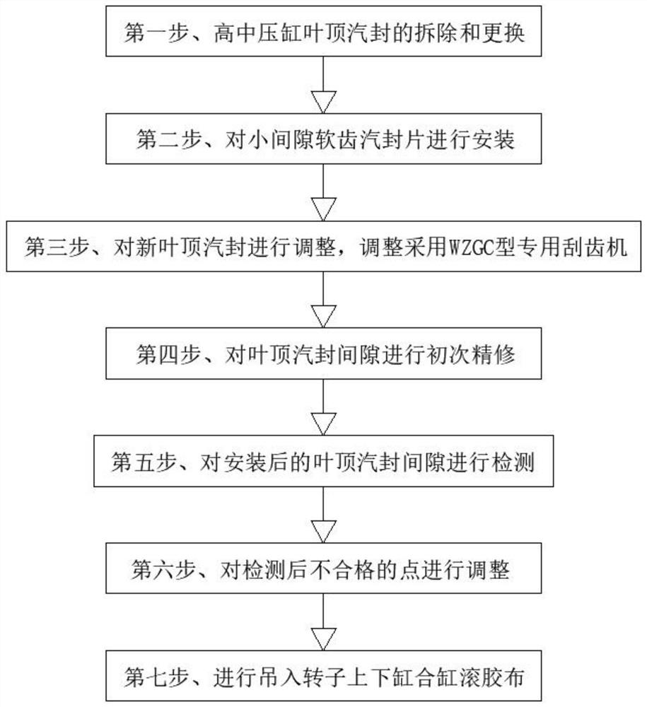
[0046] like Figure 1 ~ Figure 4 As shown, the present invention provides a method for installing a small-gap soft-tooth seal, which includes the following steps:

[0047] S1. Removal and replacement of the blade top steam seal of the high and medium pressure cylinder: use the imported special cutting machine to cut off the end of each blade top steam seal, and use the pliers and nail opener to remove all the original blade top steam seals;

[0048] S2. Install...


PUM


Abstract

The invention discloses an installation method of a small-gap soft-tooth steam seal. The installation method comprises the steps that S1, a blade top steam seal of a high and medium pressure cylinder is disassembled and replaced; S2, a small-gap soft-tooth steam seal piece is installed; S3, a new blade top steam seal is adjusted, and a WZGC type special tooth scraping machine is adopted for adjustment; S4, primary fine trimming is carried out on the gap of the blade top steam seal; S5, the gap of the installed blade top steam seal is detected; S6, unqualified points generated after detection are adjusted; and S7, a rotor is hoisted in, an upper cylinder and a lower cylinder are combined, and adhesive tape rolling is carried out. The gap between the blade top steam seal and a high and medium pressure rotor shroud is adjusted, the blade top steam seal is ground off preferentially, a steam turbine rotor shroud is protected against wear, meanwhile, the value of the gap between the blade top steam seal and the high and medium pressure rotor shroud is controlled to be small, inter-stage steam leakage losses of the high and medium pressure cylinder of a steam turbine can be reduced to the maximum degree, steam consumption of the steam turbine is reduced, the internal efficiency of the steam turbine is improved, and the energy-saving effect is obvious.

Description

technical field [0001] The invention belongs to the technical field of blade top steam seals of high and medium pressure cylinders of steam turbines, and in particular relates to an installation method of soft tooth steam seals with small gaps. Background technique [0002] The high-pressure cylinder is an integral part of the steam turbine. There are two types of single-flow and double-flow. Just like the steam turbine, the steam turbine is called a steam turbine engine abroad. The high-pressure cylinder is the initial stage when the main steam enters the cylinder. At this time, the steam pressure is high and the temperature is high, so the corresponding high-pressure cylinder has short blades and a large impeller diameter. The medium-pressure cylinder is parallel to the high-pressure cylinder and low-pressure cylinder, and the difference lies in the internal pressure. In steam turbines, they are generally connected to each other, and only multi-shafts will be separated. ...

Claims


Application Information

Patent Timeline
Patent Type & Authority Applications(China)
IPC IPC(8): F01D11/04F01D11/06F01D21/00F01D25/00
CPCF01D11/04F01D11/06F01D21/003F01D25/00
Inventor 邓志远王振明陈星马杰刘红军唐志
Owner 陕煤电力信阳有限公司
Why Eureka
Try Eureka