

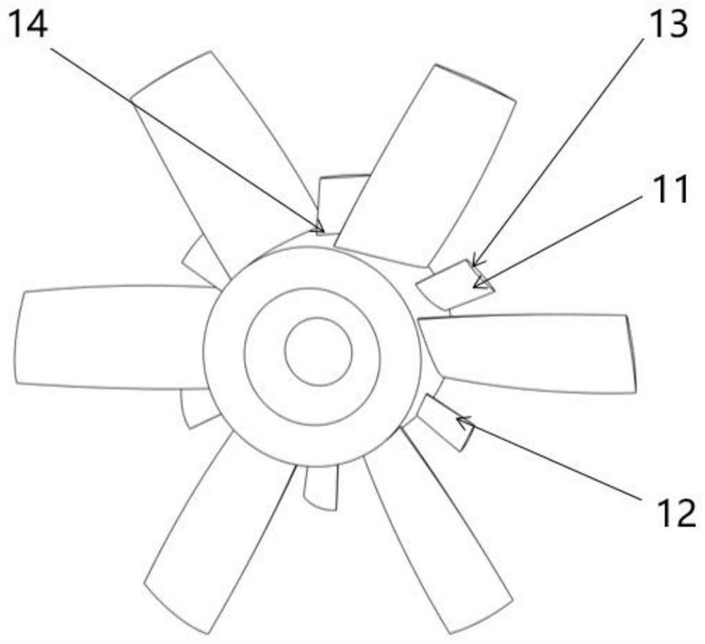
Axial flow impeller with splitter blades
A splitter vane and axial flow impeller technology, which is applied to parts of pumping devices for elastic fluids, non-variable pumps, pump components, etc., can solve the problems of complex blade structure and unfavorable processing and manufacturing, and achieve improved aerodynamics. performance, disturbance reduction, and the effect of expanding the stable operating range
- Summary
- Abstract
- Description
- Claims
- Application Information
AI Technical Summary
Problems solved by technology
Method used
Image

Examples
Embodiment 1
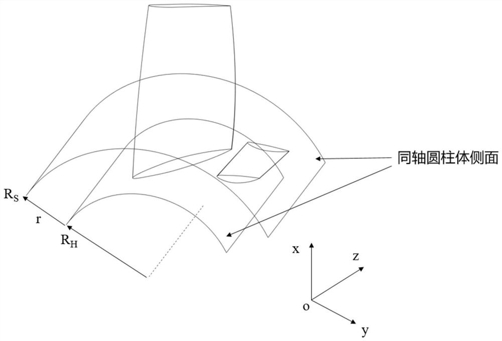
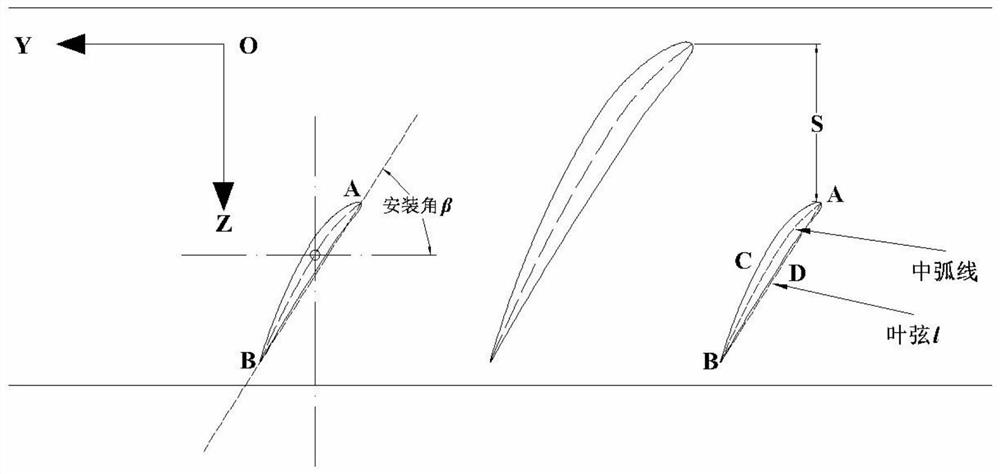
[0046] The diameter of the large blade in this embodiment is 300 mm, the number of blades is 6, and the number of splitter blades is 6. The vane installation angle of each section along the height direction of the splitter blade changes in the form of a quadratic function, and the coefficient of the quadratic function is given by The different installation angles are determined by the values of the three sections of leaf height 0%, leaf height 50% and leaf height 100%. The values are: 56.76°, 52.4° and 48.11°; the reduction factor is 0.1, and the height coefficient is 0.28, the axial position is a 25mm translation along the Z axis, and the circumferential position is a 15° rotation around the Z axis.
Embodiment 2
[0048] The diameter of the large blade in this embodiment is 300 mm, the number of blades is 6, and the number of splitter blades is 6. The vane installation angle of each section along the height direction of the splitter blade changes in the form of a quadratic function, and the coefficient of the quadratic function is given by The different installation angles are determined by the values of the three sections of leaf height 0%, leaf height 50% and leaf height 100%. The values are: 56.76°, 52.4° and 48.11°; the reduction factor is 0.5, and the height coefficient is 0.28, the axial position is a 25mm translation along the Z axis, and the circumferential position is a 30° rotation around the Z axis.
Embodiment 3
[0050] The diameter of the large blade in this embodiment is 300 mm, the number of blades is 6, and the number of splitter blades is 6. The vane installation angle of each section along the height direction of the splitter blade changes in the form of a quadratic function, and the coefficient of the quadratic function is given by The different installation angles are determined by the values of the three sections of leaf height 0%, leaf height 50% and leaf height 100%. The values are: 56.76°, 46.1° and 35.11°; the reduction factor is 0.5, and the height coefficient is 0.70, the axial position is a 25mm translation along the Z axis, and the circumferential position is a 30° rotation around the Z axis.
[0051] Image 6 with Figure 7 It is the flow-total pressure efficiency curve and the flow-total pressure curve of the prototype (that is, without splitter vanes) and embodiments 1, 2, and 3. When the flow rate is less than 0.7kg / s, the total pressure efficiency and total ...
PUM
 Abstract
Description
Claims
Application Information