
Improved thrust ball bearing suitable for heavy-load low-speed working condition

A thrust ball bearing, heavy-duty low-speed technology, applied in the field of bearings, can solve the problems of affecting the progress of mechanical work, reducing work efficiency, time-consuming and labor-intensive, etc., and achieve the effect of reducing cleaning steps, improving work efficiency and simplifying steps

Active Publication Date: 2021-11-16
聊城鲁寰轴承有限公司
View PDF6 Cites 1 Cited by
  • Summary
  • Abstract
  • Description
  • Claims
  • Application Information

AI Technical Summary

Problems solved by technology

[0005] In order to solve the above technical problems, the present invention provides an improved thrust ball bearing suitable for heavy-duty low-speed working conditions, so as to solve the problem that the existing thrust ball bearings need to be lubricated regularly when the bearings are in use. Impurities need to be disassembled to clean up, which is time-consuming and labor-intensive, and reduces work efficiency. When the bearing is installed, the required components are installed on the shaft, and it is easy to make the components shift and need to be adjusted again, which affects the working progress of the machine. The problem

Method used


Image

  • Improved thrust ball bearing suitable for heavy-load low-speed working condition
  • Improved thrust ball bearing suitable for heavy-load low-speed working condition
  • Improved thrust ball bearing suitable for heavy-load low-speed working condition

Examples


Embodiment

[0033] as attached figure 1 to attach Figure 7 Shown:

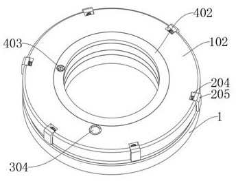
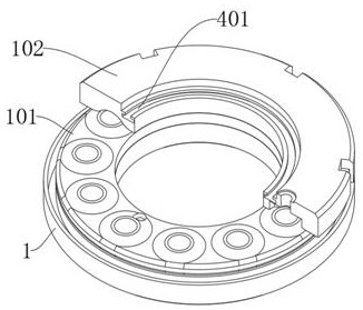
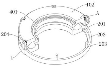
[0034] The present invention provides an improved thrust ball bearing suitable for heavy-duty low-speed working conditions, comprising: a main body 1, an arc-shaped groove is provided on the top of the main body 1, and a connecting piece 2 is installed on the top of the main body 1; the connecting piece 2, The chute 201 in the connecting piece 2 is arranged on the top of the main body 1, and the top groove 204 in the connecting piece 2 is set at the edge position of the top plate 102; the cleaning piece 3, the cleaning piece 3 is installed inside the main body 1 and the top plate 102, and The inner groove 301 in the cleaning part 3 is located at the top of the main body 1 and the bottom of the top plate 102; top.

[0035] Wherein, the main body 1 includes: an inner plate 101, the inside of the inner plate 101 is installed with evenly arranged balls, and the inner plate 101 is installed on the top of the main body 1, a...


PUM


Abstract

The invention provides an improved thrust ball bearing suitable for a heavy-load and low-speed working condition, relates to the technical field of bearings, and aims to solve the problems that when an existing thrust ball bearing is used, impurities on bearing balls need to be removed through disassembly, and time and labor are wasted. The improved thrust ball bearing comprises a main body, a connecting piece, a cleaning piece and a smearing piece, and an arc-shaped groove is formed in the top of the main body; the connecting piece is mounted at the top of the main body; a sliding groove in the connecting piece is formed in the top of the main body, and a top groove in the connecting piece is formed in the edge position of a top plate; the cleaning piece is mounted in the main body and the top plate, and an inner groove in the cleaning piece is formed in the top of the main body and the bottom of the top plate; and the smearing piece is installed on the top of the top plate, and a flow guide groove in the smearing piece is formed in the top of an inner plate. The arc-shaped structures at the outer ends of scrapers are attached to balls installed in the inner plates, impurities generated when the scrapers clean the balls are discharged through gaps between the inner plates, and the steps of bearing disassembly and re-cleaning are reduced.

Description

technical field [0001] The invention belongs to the technical field of bearings, and more specifically relates to an improved thrust ball bearing suitable for heavy-load and low-speed working conditions. Background technique [0002] Thrust ball bearing is a separable bearing. The shaft ring and seat ring can be separated from the cage and steel ball components. The shaft ring, seat ring and rolling elements are separated and can be assembled and disassembled separately. [0003] For example, the application number: CN201410511160.2 relates to a thrust ball bearing, including a shaft ring, two seat rings, steel balls, and two cages. The shaft ring is installed between the two seat rings, and the two seat rings and A steel ball cage is arranged between the shaft rings, and one ring is assembled by more than three equally divided sector blocks, and a sealing groove is arranged between the seat ring and the shaft ring. The sealing groove is filled with a sealing gasket, and t...

Claims


Application Information

Patent Timeline
IPC IPC(8): F16C19/12F16C33/58F16C33/66F16C35/078B08B1/02
CPCF16C19/12F16C33/581F16C33/6659F16C33/6681F16C35/078F16C2235/00B08B1/20B08B1/165
Inventor 张新法马云峰
Owner 聊城鲁寰轴承有限公司
Learn More