Break-off valve protective sleeve
A technology of protective sleeve and pull-off valve, applied in the field of protective sleeve, can solve the problems of explosion or fire, scratches on the surface of the chassis of the fuel dispenser, etc., and achieve the effect of stabilizing the positional relationship
- Summary
- Abstract
- Description
- Claims
- Application Information
AI Technical Summary
Problems solved by technology
Method used
Image

Examples
Embodiment 1
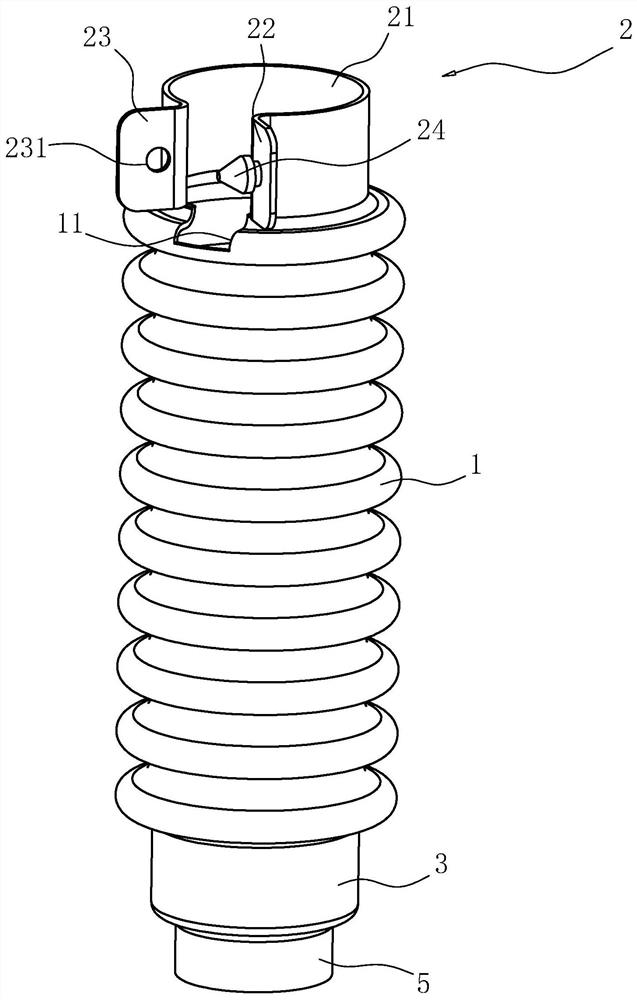
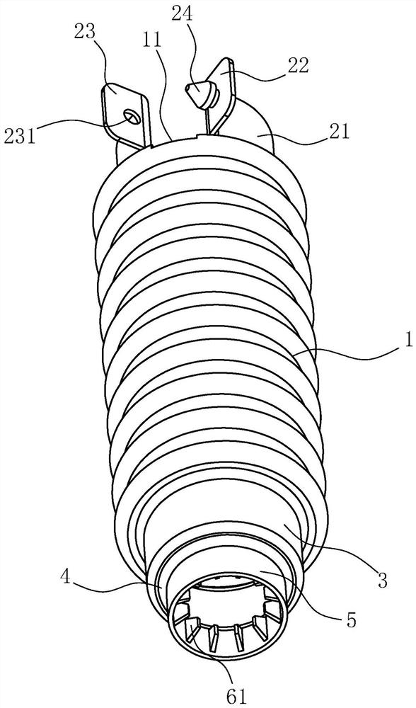
[0036] refer to figure 1 and figure 2 , the application provides a breakaway valve protection sleeve, including a sleeve 1 and a clamping assembly 2 for fixing the sleeve 1 on the pipeline. The sleeve 1 is made of elastic material, and the elastic material can be rubber or elastic Resin material; set the sleeve 1 on the outside of the breakaway valve, and fix the positional relationship between the sleeve 1 and the pipeline through the clamping component 2; due to the elasticity of the sleeve 1, the contact between the breakaway valve and the fuel dispenser is avoided Rigid collision occurs between the chassis, and the outer casing 1 can buffer the impact of the collision between the breakaway valve and the fuel dispenser, thereby reducing the generation of sparks caused by the collision between the breakaway valve and the chassis and causing the chassis to Potential for scratches on the surface.
[0037] Further, the clamping assembly 2 includes a clasp 21 integrally forme...
Embodiment 2
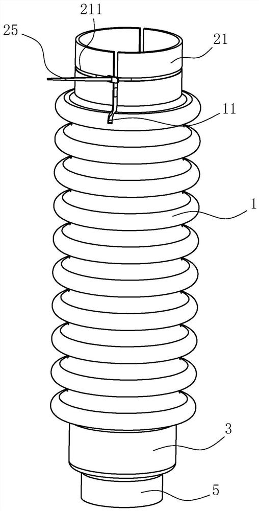
[0046] refer to image 3 The difference between this embodiment and the first embodiment is that the clamping assembly 2 is different. It is further set that the clamping assembly 2 includes two semicircular rings 21 oppositely arranged, and the rings 21 are integrally formed on the sleeve 1 away from the clamping One end of the tube 5 is tightened and two clasping rings 21 are respectively arranged on both sides of the axis of the casing 1, and there is a gap between the two clasping rings 21 for the two clasping rings 21 to move toward each other and affect the casing 1 to generate Elastic deformation; two deformation grooves 11 are provided on the end of the casing 1 close to the ring 21 and communicate with the corresponding gaps between the two rings 21 respectively; An annular card slot 211 is provided, and a cable tie 25 is embedded inside the card slot 211 .
[0047] When it is necessary to fix the sleeve 1 on the pipeline, the cable tie 25 is tightened so that the di...
Embodiment 3
[0049] refer to Figure 4 , the difference between this embodiment and the first embodiment is that the buckle 24 is different from the buckle hole 231. It is further explained that the buckle 24 is a square-shaped buckle 24, and the cross-sectional area of the buckle 24 is along the direction from close to far away. The direction of the first card 22 gradually becomes smaller; the card hole 231 is a rectangular card hole 231, and the cross-sectional area of the card hole 231 is smaller than the cross-sectional area of the buckle 24 near the first card 22; when the buckle 24 intends to pass through the card hole 231, the slope of the buckle 24 is squeezed against the hole wall of the locking hole 231, and the buckle 24 and the hole wall of the locking hole 231 are elastically deformed at the same time until the buckle 24 completely passes through the locking hole 231 and reaches the second card 23 away from it. One side of the second card 23.
PUM
 Abstract
Description
Claims
Application Information