Metal waste processing device

A technology for processing equipment and metal waste, which is applied in the fields of manufacturing tools, presses, grain processing, etc., can solve the problems of inconvenient transportation and recycling processing, loose waste density, scratches of metal waste by construction personnel, etc., to reduce the scratches of metal waste. the effect of the possibility of

Inactive Publication Date: 2020-02-21
徐州给力磁业有限公司
View PDF8 Cites 3 Cited by
  • Summary
  • Abstract
  • Description
  • Claims
  • Application Information

AI Technical Summary

Problems solved by technology

[0002] Various industries will produce some waste in the manufacturing process. In the process of mechanical production and processing, some processing waste such as steel shavings, coiled wire, and cutting slag will be produced. In order to meet the development needs of an energy-saving and environmentally friendly society, generally These wastes are recycled and reused, but because these wastes are loose in density and occupy a large space, it is very inconvenient to transport and recycle.
[0003] In the prior art, when people recycle this kind of metal waste, they mostly reduce the bulkiness of the waste by manually pushing the waste. Often in the process of manual operation, not only the operation is laborious, but also the construction workers will be scraped by these metal waste. Injury, therefore, it is necessary to invent a metal scrap processing device to solve the above problems

Method used


Image

  • Metal waste processing device
  • Metal waste processing device
  • Metal waste processing device

Examples


Embodiment Construction

[0016] The technical solutions in the embodiments of the present invention will be clearly and completely described below with reference to the accompanying drawings in the embodiments of the present invention. Obviously, the described embodiments are only a part of the embodiments of the present invention, but not all of the embodiments. Based on the embodiments of the present invention, all other embodiments obtained by those of ordinary skill in the art without creative efforts shall fall within the protection scope of the present invention.

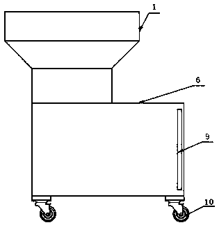
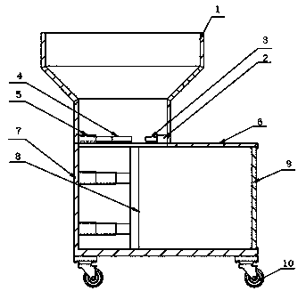
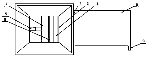
[0017] according to Figure 1-3 The shown metal scrap processing device includes a feeding funnel 1, a fixing plate 2 is fixedly arranged on a side wall inside the feeding funnel 1, and a first serrated knife 3 is fixedly fixed on one side of the fixing plate 2, so the One side of the first serrated knife 3 is provided with a second serrated knife 4, one side of the second serrated knife 4 is provided with a first bamboo-type electric...


PUM


Abstract

The invention discloses a metal waste processing device, and particularly relates to the technical field of metal waste processing. The metal waste processing device comprises a feeding funnel; a fixed plate is fixedly arranged on one side wall inside the feeding funnel; a first sawtooth knife is fixedly arranged on one side of the fixed plate; a second sawtooth knife is arranged on one side of the first sawtooth knife; a first bamboo joint type electric push rod is arranged on one side of the second sawtooth knife; an extrusion box is fixedly arranged at the bottom of the feeding funnel; a second bamboo joint type electric push rod is arranged in the extrusion box; the second bamboo joint type electric push rod is arranged at the bottom of the first bamboo joint type electric push rod; and an extrusion plate is arranged on one side of the second bamboo joint type electric push rod. According to the metal waste processing device, the feeding funnel is moved below a working machine, sothat metal waste directly enters into the extrusion box through the feeding funnel and is extruded into blocks by the extrusion plate, the whole extrusion process does not need manual operation, the operation is simple, the working efficiency is high, and the safety of construction personnel is effectively guaranteed.

Description

technical field [0001] The present invention relates to the technical field of metal scrap processing, and more particularly, to a metal scrap processing device. Background technique [0002] Various industries will generate some waste in the production and manufacturing process. In the process of mechanical production and processing, there will be some processing wastes with loose density such as steel shavings, coiled wires, cutting slag and other processing wastes. In order to meet the development needs of an energy-saving and environmentally friendly society, generally These wastes are recycled and reused, but due to their loose density and occupying a large space, it is very inconvenient to transport and recycle. [0003] In the prior art, when people recycle such metal scraps, they mostly reduce the bulkiness of the scraps by manually pushing the scraps. In the process of manual operation, not only the operation is laborious, but the construction workers will also be s...

Claims


Application Information

Patent Timeline
Patent Type & Authority Applications(China)
IPC IPC(8): B30B9/32B30B15/30B02C18/02B02C18/04
CPCB02C18/02B02C18/04B30B9/326B30B9/327B30B15/30
Inventor 王宏伟
Owner 徐州给力磁业有限公司
Why Eureka
Try Eureka