
Small pneumatic surface coating equipment

A surface coating and pneumatic technology, which is applied to the device and coating of the surface coating liquid, can solve the problems of error not exceeding 0.1mm, poor consistency of coating quality, etc., to achieve convenient use and adjustment, and less environmental pollution , to ensure the effect of uniformity and adhesion strength

Active Publication Date: 2021-11-19
SHAANXI BAOCHENG AVIATION INSTR
View PDF13 Cites 2 Cited by
  • Summary
  • Abstract
  • Description
  • Claims
  • Application Information

AI Technical Summary

Problems solved by technology

[0002] In actual production, it is necessary to carry out surface coating treatment on the inner and outer surfaces of some parts, but in the process of coating treatment, due to the high requirements on the coating thickness of the inner holes and grooves of the parts, it is necessary to ensure the thickness of the entire coating layer The error cannot exceed 0.1mm. Therefore, when coating, it is necessary to strictly control various process parameters to ensure the uniformity of the coating layer thickness and adhesion strength of the parts. When the powdery coating powder is coated on the parts , the suspension height and concentration of the coating powder have a great influence on the coating quality. At present, many manual coating operations are used, resulting in poor coating quality and consistency. Therefore, it is necessary to improve the above problems

Method used


Image

  • Small pneumatic surface coating equipment
  • Small pneumatic surface coating equipment
  • Small pneumatic surface coating equipment

Examples


Embodiment Construction

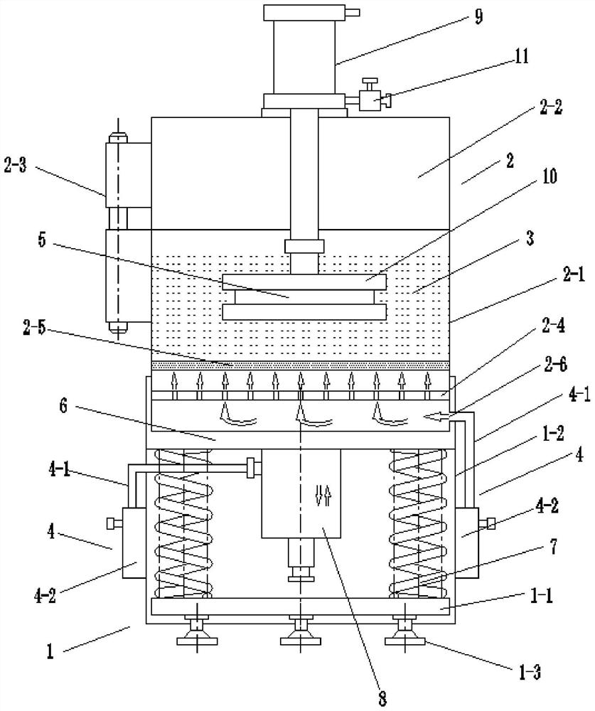
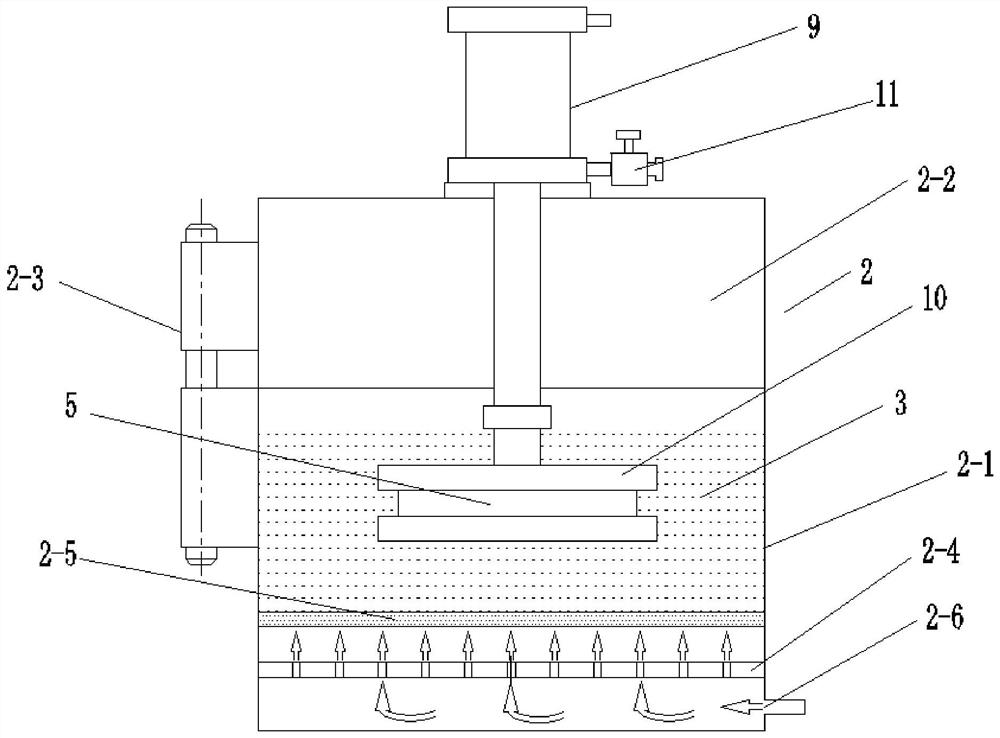
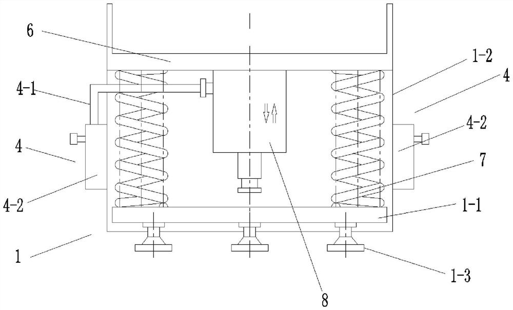
[0023] Attached below Figure 1-4 An embodiment of the present invention is described so as to clearly and completely describe the technical solution. Obviously, the described embodiment is only a part of the embodiments of the present invention, rather than all the embodiments.

[0024] In describing the present invention, it should be understood that the terms "upper", "lower", "front", "rear", "left", "right", "top", "bottom", "inner", " The orientation or positional relationship indicated by "outside", etc. is based on the orientation or positional relationship shown in the drawings, which is only for the convenience of describing the present invention and simplifying the description, rather than indicating or implying that the referred device or element must have a specific orientation, so as to Specific orientation configurations and operations, therefore, are not to be construed as limitations of the invention.

[0025] Small pneumatic surface coating equipment such as...


PUM


Abstract

The invention provides small pneumatic surface coating equipment. A vibration device is installed in a supporting frame, the lower end of a coating barrel is installed on the vibration device in a matched mode, and a flow-adjustable air supply pipe which communicates with the coating barrel and is used for controlling coating powder in the coating barrel to be in a suspended state is arranged on the wall of a shell on one side of the supporting frame; and a lifting driving device with the lower end connected with a part in the coating barrel is arranged on the coating barrel, and the lifting driving device is used for driving the part to lift. The coating barrel which is provided with the lifting device and connected with the part is mounted on the vibration device of the supporting frame in a matched mode, the vibration device provides vibration for the coating barrel, and meanwhile the lifting device drives the part which moves downwards to conduct surface coating work in the coating barrel. The problem that in the part coating process, the thickness precision of a coating layer is difficult to guarantee is solved, controllable operation of the vibration frequency, the vibration strength and the suspension height and concentration of coating powder can be achieved through the flow-adjustable air supply pipe and the vibration device, and the production process requirements for surface coating of various small parts are conveniently met.

Description

technical field [0001] The invention belongs to the technical field of surface coating, in particular to a small pneumatic surface coating equipment. Background technique [0002] In actual production, it is necessary to carry out surface coating treatment on the inner and outer surfaces of some parts, but in the process of coating treatment, due to the high requirements on the coating thickness of the inner holes and grooves of the parts, it is necessary to ensure the thickness of the entire coating layer The error cannot exceed 0.1mm. Therefore, when coating, it is necessary to strictly control various process parameters to ensure the uniformity of the coating layer thickness and adhesion strength of the parts. When the powdery coating powder is coated on the parts , The suspension height and concentration of the coating powder have a great influence on the coating quality. At present, many manual coating operations are used, resulting in poor coating quality and consisten...

Claims


Application Information

Patent Timeline
Patent Type & Authority Applications(China)
IPC IPC(8): B05C19/04B05C19/06
CPCB05C19/04B05C19/06Y02P70/10
Inventor 狄亚辉魏劲春龙健康徐爱民郭万庆贾晓军李平王刚吴天祥
Owner SHAANXI BAOCHENG AVIATION INSTR
Learn More