
Parts disc wheel tool changer for hardware parts processing

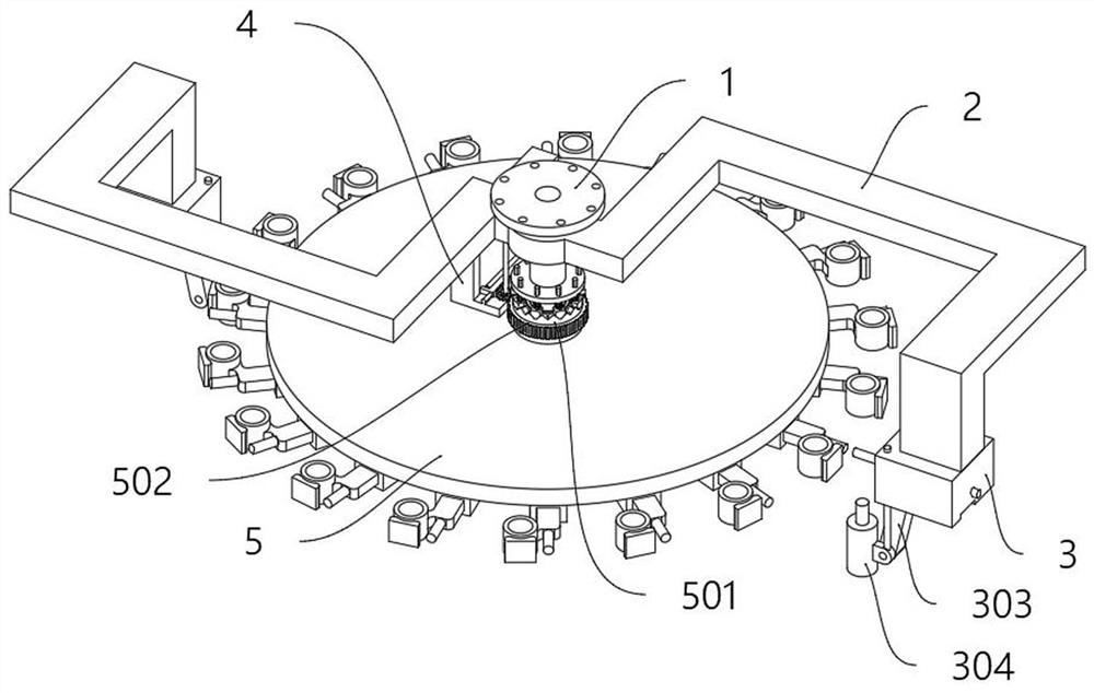
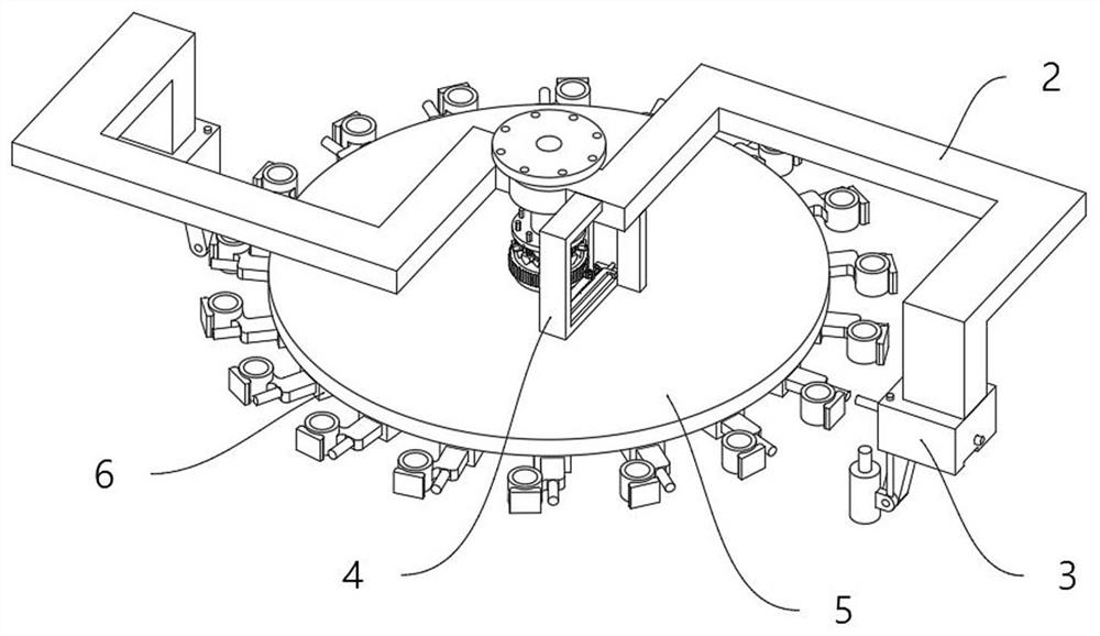
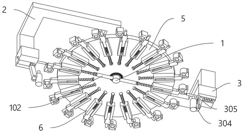
A tool changer, disc wheel technology, applied in metal processing mechanical parts, metal processing equipment, positioning devices, etc., can solve the problem of unfavorable loading or replacement, no control structure for automatic docking and lifting, no lifting coordination function, etc. problems, to avoid potential safety hazards and achieve the effect of high degree of automation

Active Publication Date: 2021-12-24
南通科邦机械有限公司
View PDF6 Cites 0 Cited by
  • Summary
  • Abstract
  • Description
  • Claims
  • Application Information

AI Technical Summary

Problems solved by technology

[0006] The purpose of the present invention is to provide an accessory disk-wheel tool changer for processing hardware accessories, so as to solve the problem that the currently used tool changer proposed in the above-mentioned background technology is mainly a disc structure, which is mainly controlled by servo, and does not have automatic docking and lifting. The control structure does not have the lifting and matching function of automatically feeding the workpiece at a fixed point and installing the workpiece in the cutter head, which is not conducive to fast loading or replacement.

Method used


Image

  • Parts disc wheel tool changer for hardware parts processing
  • Parts disc wheel tool changer for hardware parts processing
  • Parts disc wheel tool changer for hardware parts processing

Examples


Embodiment Construction

[0030] The following will clearly and completely describe the technical solutions in the embodiments of the present invention with reference to the accompanying drawings in the embodiments of the present invention. Obviously, the described embodiments are only some, not all, embodiments of the present invention.

[0031] In the description of the present invention, unless otherwise stated, the meaning of "plurality" is two or more; the terms "upper", "lower", "left", "right", "inner", "outer" , "front end", "rear end", "head", "tail", etc. indicate the orientation or positional relationship based on the orientation or positional relationship shown in the drawings, and are only for the convenience of describing the present invention and simplifying the description, rather than Nothing indicating or implying that a referenced device or element must have a particular orientation, be constructed, and operate in a particular orientation should therefore not be construed as limiting ...


PUM


Abstract

The invention discloses an accessory disk-wheel tool changing device for processing hardware accessories, relates to the technical field of tool changing for machine tools, and solves the problem that the currently used tool changing device is mainly a disc structure, which is mainly controlled by a servo, and does not have automatic docking and lifting. Problems with control structures. The accessory disk wheel tool changer for hardware accessories processing, including the main assembly pipe, the top of the main assembly pipe is a flange structure; the station frame, the station frame is U-shaped and symmetrical on both sides structure, and the two ends of the station frame turn downwards; through the arrangement of racks, internal ratchet gears and driven gears, the automatic fixed-point control locking function is provided for the tool changer, and the bottom of the V-shaped groove and the self-locking block Matching, by setting the self-locking block and the assembly cylinder, the spring outside the hexagonal shaft is used to generate the self-locking function, and then the control of the angular position of the cutterhead is realized. The cutterhead can be switched and adjusted within 18 angles, and the angle can be adjusted. Perform steering control.

Description

technical field [0001] The invention relates to the technical field of tool change for machine tools, in particular to an accessory disc-wheel tool changer for processing hardware accessories. Background technique [0002] A milling cutter is a rotating tool with one or more teeth for milling. The main body is a cylindrical structure. It is generally installed in the cutter head in the machine tool. The cutter head has a locking structure that can be controlled by electricity or manually. The tool is fixed by clamping with three-jaw structure. [0003] The currently used tool changing device is mainly a disc structure, which is mainly controlled by servo, does not have the control structure of automatic docking and lifting, and does not have the lifting and matching function of automatically feeding the workpiece at a fixed point and installing the workpiece in the cutter head, which is not conducive to rapid Refill or replace. [0004] Therefore, the existing requirements...

Claims


Application Information

Patent Timeline
IPC IPC(8): B23Q3/157
CPCB23Q3/157
Inventor 戴金山
Owner 南通科邦机械有限公司
Learn More