Supercharge Your Innovation With Domain-Expert AI Agents!

Output shaft base machining fixing device and using method therefor

A fixing device and output shaft technology, applied in workpiece clamping devices, manufacturing tools, etc., can solve the problems of high scrap rate of the output shaft base, inconvenient rapid processing operations, low degree of automation, etc., to achieve automatic clamping operations, reduce The effect of reducing the burden on workers and reducing the scrap rate

Pending Publication Date: 2021-11-19
张家港海运金属冷挤压有限公司
View PDF8 Cites 0 Cited by
  • Summary
  • Abstract
  • Description
  • Claims
  • Application Information

AI Technical Summary

Problems solved by technology

Usually, the output shaft base needs to be processed, and the output shaft base needs to be fixed during processing. The existing output shaft processing and fixing devices often have the following problems in the processing process: 1. The existing output shaft processing and fixing devices are extremely difficult during use. It is easy to cause damage to the output shaft, resulting in a high scrap rate of the output shaft base, thereby increasing the processing cost; 2. The existing output shaft processing and fixing device is inconvenient to perform all-round processing operations on the output shaft base, and it is not convenient to realize subsequent rapid processing 3. The existing output shaft processing and fixing devices often require manual control of the operating equipment, resulting in a low degree of automation and increasing the burden on laborers

Method used


Image

  • Output shaft base machining fixing device and using method therefor
  • Output shaft base machining fixing device and using method therefor
  • Output shaft base machining fixing device and using method therefor

Examples


Embodiment Construction

[0030] In order to make the technical means, creative features, goals and effects achieved by the present invention easy to understand, the present invention will be further described below in conjunction with specific embodiments.

[0031] In the description of the present invention, it should be noted that the terms "upper", "lower", "inner", "outer", "front end", "rear end", "both ends", "one end", "another end" The orientation or positional relationship indicated by etc. is based on the orientation or positional relationship shown in the drawings, and is only for the convenience of describing the present invention and simplifying the description, rather than indicating or implying that the referred device or element must have a specific orientation, use a specific Azimuth configuration and operation, therefore, should not be construed as limiting the invention. In addition, the terms "first" and "second" are used for descriptive purposes only, and should not be understood ...


PUM


Abstract

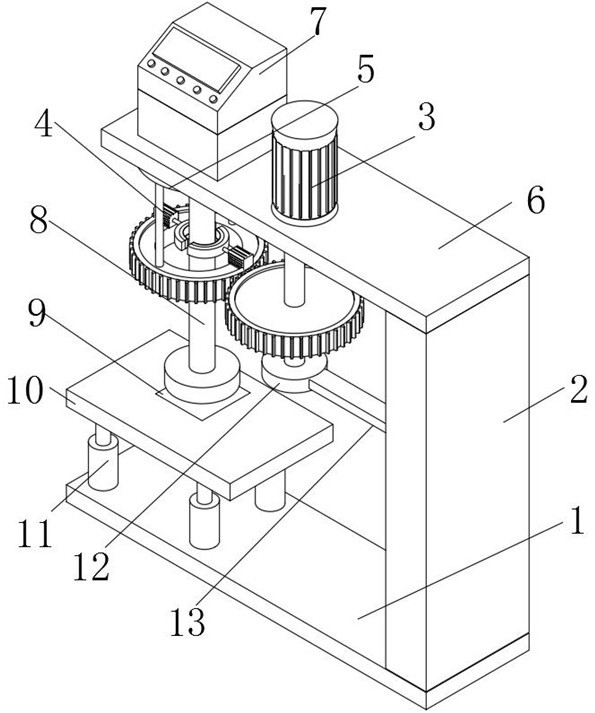
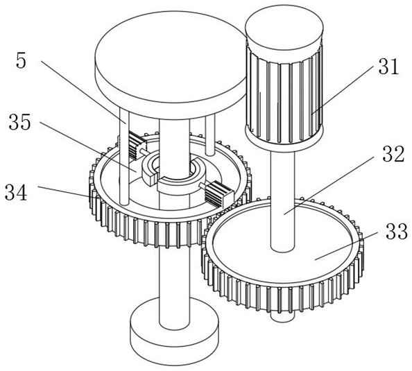
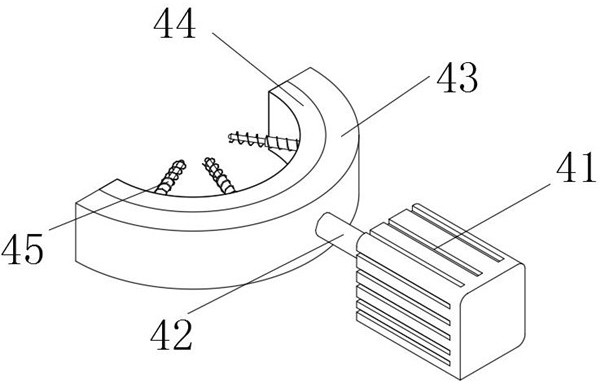
The invention discloses an output shaft base machining fixing device and a using method therefor. The output shaft base machining fixing device comprises a bottom plate; a side plate is fixedly installed on the right side of the upper end of the bottom plate; a top plate is fixedly connected to the upper end of the side plate; a rotating mechanism penetrates through the middle of the top plate; a limiting mechanism and two fixing mechanisms are fixedly installed at the upper end of the rotating mechanism; the two fixing mechanisms are distributed oppositely; the upper end of the limiting mechanism is fixedly connected with the lower end of the top plate; a control table is fixedly installed on the left portion of the upper end of the top plate; four hydraulic lifting pieces are fixedly installed on the left portion of the upper end of the bottom plate; a platform is fixedly installed at the upper ends of the four hydraulic lifting pieces jointly; a pressure sensor is embedded in the middle of the upper end of the platform; and an output shaft base piece is placed at the upper end of the pressure sensor. According to the output shaft base machining fixing device and the using method therefor, the rejection rate of an output shaft base is reduced, the machining cost is reduced, the follow-up machining operation speed is guaranteed, and the automation degree of the fixing device is improved.

Description

technical field [0001] The invention relates to the technical field of output shaft base processing, in particular to an output shaft base processing and fixing device and a use method thereof. Background technique [0002] The output shaft is the shaft that outputs power. Like a motor, it converts electric power, hydraulic pressure or air pressure into mechanical power, and the output shaft transmits torque. The output shaft is often associated with the base. Usually, the output shaft base needs to be processed, and the output shaft base needs to be fixed during processing. The existing output shaft processing and fixing devices often have the following problems in the processing process: 1. The existing output shaft processing and fixing devices are extremely difficult during use. It is easy to cause damage to the output shaft, resulting in a high scrap rate of the output shaft base, thereby increasing the processing cost; 2. The existing output shaft processing and fixi...

Claims


Application Information

Patent Timeline
IPC IPC(8): B25B11/00
CPCB25B11/00
Inventor 唐成唐正兴安仁军
Owner 张家港海运金属冷挤压有限公司
Features
  • R&D
  • Intellectual Property
  • Life Sciences
  • Materials
  • Tech Scout
  • Unparalleled Data Quality
  • Higher Quality Content
  • 60% Fewer Hallucinations
Learn More