

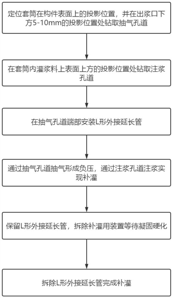
Supplementary filling treatment method for sleeve grouting defect under bent-pipe-shaped slurry outlet hole channel
A technology of sleeve grouting and tunneling, which is applied in the processing of building materials, construction, building reinforcements, etc., and can solve the problems of being unable to arrange grouting pipes at the same time, and unable to replenish grouting, etc.
- Summary
- Abstract
- Description
- Claims
- Application Information
AI Technical Summary
Problems solved by technology
Method used
Image

Examples
Embodiment Construction
[0036] The present invention will be further described below in conjunction with the accompanying drawings and specific embodiments, so that those skilled in the art can better understand the present invention and implement it, but the examples given are not intended to limit the present invention.
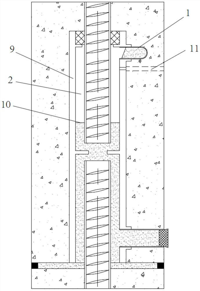
[0037] refer to Figure 1 to Figure 7 As shown, an embodiment of the method for refilling and remediating sleeve grouting defects 2 in the case where the grout outlet channel 1 is an elbow according to the present invention, the auxiliary refilling device used includes an L-shaped external extension pipe 3, an electric grouting device and Flexible sealing material 8, the electric grouting device includes grouting pipe 4, grouting cylinder 5, air extraction pipe 6, air extraction cylinder 7 and electric push-pull, the electric push-pull can independently push the grouting cylinder for grouting, and pull the air extraction cylinder for air extraction And at the same time, push the g...
PUM
 Abstract
Description
Claims
Application Information