
Intelligent clamping and laying equipment for practical training of students

A practical and intelligent technology, applied in the field of plastering, can solve problems such as waste of raw materials, waste of materials, and mechanical failure of dirty equipment

Active Publication Date: 2021-11-19
上海震旦职业学院有限公司 +1
View PDF6 Cites 0 Cited by
  • Summary
  • Abstract
  • Description
  • Claims
  • Application Information

AI Technical Summary

Problems solved by technology

[0002] At present, in the process of building interior walls, the construction efficiency of manual plastering and spraying is low, mainly relying on the shortcomings of operators, and is gradually replaced by robots with smart devices; for the current process of building walls with smart devices, Intelligent robotic arms with multi-joints are gradually being widely used; a typical six-joint arm can realize the translation of the clamped object within a certain range of planes, and has the space movements required for plastering and spraying; but the cooperation with the six-joint robotic arm The execution end of the plastering and spraying mechanism is not perfect, and there is no special customization for the six-joint robotic arm. At present, the following problems still exist in the implementation:
[0003] First, there is a drop when plastering, causing waste of materials
[0004] Second, because there are air bubbles in the feeding pipe, there will be splashing when spraying the material, which will easily dirty the equipment and cause mechanical failure, and also waste raw materials

Method used


Image

  • Intelligent clamping and laying equipment for practical training of students
  • Intelligent clamping and laying equipment for practical training of students
  • Intelligent clamping and laying equipment for practical training of students

Examples


Embodiment approach

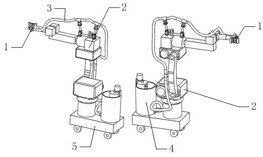
[0082]Implementation mode: when using the equipment designed in the present invention to scrape walls, control the second motor 75 to work, the second motor 75 will drive the sixth gear 76 to rotate, the sixth gear 76 will drive the seventh gear 77 to rotate, the seventh The rotation of the gear 77 drives the rotation of the installation rod 79, and the rotation of the installation rod 79 drives the rotation of the rotating shell 74. At the same time, the rotation of the installation rod 79 drives the rotation of the fixed rod 83 installed on it, and then drives the rotation of the second steady flow shell 84 thereon; through the rotation of the rotation shell 74 The rotation can stir the air bubbles in the paint entering the rotating shell 74 to reduce the distribution of the air bubbles; at the same time, the second steady flow shell 84 installed on the mounting rod 79 can absorb the air bubbles in the paint.

[0083] Then the paint is sprayed into a part of the wall through ...


PUM


Abstract

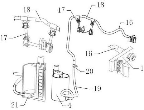
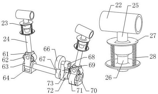
The invention belongs to the technical field of plastering, and particularly relates to intelligent clamping and laying equipment for practical training of students. The intelligent clamping and laying equipment comprises a plastering spraying execution end, a six-joint mechanical arm, a material conveying pipe, a material barrel and a travelling platform, wherein a second motor works to drive a sixth gear to rotate, the sixth gear rotates to drive a seventh gear to rotate, the seventh gear rotates to drive an installing rod to rotate, the installing rod drives a rotating shell to rotate, meanwhile, the installing rod rotates to drive a fixed rod installed on the installing rod to rotate, then a second flow stabilizing shell on the installing rod is driven to rotate, through rotation of the rotating shell, bubbles in coating entering the rotating shell can be stirred, distribution of the bubbles is reduced, and meanwhile, the bubbles in the coating are absorbed through a second flow stabilizing shell installed on the installing rod. According to the intelligent clamping and laying equipment, the coating enters the rotating shell through a notch and does not enter the rotating shell from the upper side, and the design can ensure that the coating entering the rotating shell from the upper side does not press the bubbles in the coating or press the bubbles into the rotating shell under the action of gravity.

Description

technical field [0001] The invention belongs to the technical field of plastering, and in particular relates to an intelligent clamping and masonry equipment for students' practical training. Background technique [0002] At present, in the process of building interior walls, the construction efficiency of manual plastering and spraying is low, mainly relying on the shortcomings of operators, and is gradually replaced by robots with smart devices; for the current process of building walls with smart devices, Intelligent robotic arms with multi-joints are gradually being widely used; a typical six-joint arm can realize the translation of the clamped object within a certain range of planes, and has the space movements required for plastering and spraying; but the cooperation with the six-joint robotic arm The execution end of the plastering and spraying mechanism is not perfect, and there is no special customization for the six-joint robotic arm. At present, the following prob...

Claims


Application Information

Patent Timeline
Patent Type & Authority Applications(China)
IPC IPC(8): E04F21/08E04F21/16B05B9/04B05B15/00B05B15/25G09B9/00
CPCE04F21/08E04F21/16B05B9/0403B05B15/00B05B15/25G09B9/00
Inventor 陈锡宝袁明付奕陈凌峰周芸孙晓艳汪聪晏如曼武楠朱勇
Owner 上海震旦职业学院有限公司
Learn More