
Mass concrete condensation system

A technology of mass concrete and condensing system, applied in the direction of infrastructure engineering, architecture, building construction, etc., can solve the problems of poor cooling effect, complex heat pump structure, unsuitable construction site, etc., to achieve practical and reliable, Water saving and practical effect

Inactive Publication Date: 2021-11-19
李硕
View PDF6 Cites 0 Cited by
  • Summary
  • Abstract
  • Description
  • Claims
  • Application Information

AI Technical Summary

Problems solved by technology

However, although the existing cooling equipment has high cooling efficiency, most of them use complex structures such as heat pumps. Professionals are required for daily maintenance, and workers cannot perform basic maintenance on the spot. Said that it is not actually applicable on the construction site
In addition, the location of the general construction site is relatively remote, and it is inconvenient to use water. The traditional method of directly spraying water on the concrete to cool down, wastes water resources, and the cooling effect is not good, and it is easy to accumulate water

Method used


Image

  • Mass concrete condensation system
  • Mass concrete condensation system
  • Mass concrete condensation system

Examples


Embodiment Construction

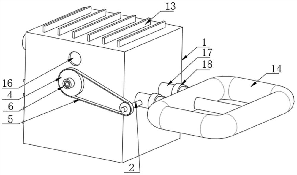
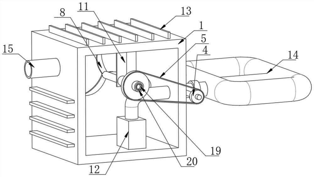
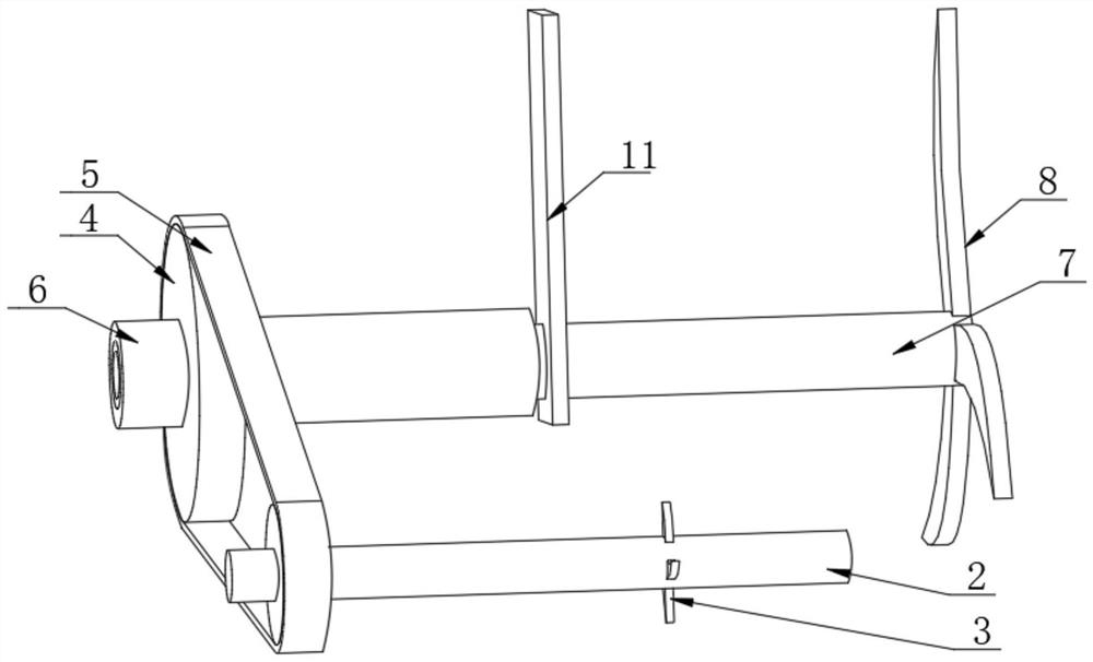
[0021] For the mass concrete condensing system provided by the embodiments of the present invention, please refer to figure 1 , figure 2 , image 3 and Figure 4 , comprising a box body 1 and a cooling tube 14 installed outside the box body 1 for cooling the concrete. The cooling tube 14 can cool and condense the concrete when it is inserted into the concrete or moves in the concrete, or , before pouring, the cooling pipe 14 is directly placed in the middle of the tank storing concrete for central cooling, and the temperature difference after the concrete flows out is as small as possible. The difference is smaller, and the performance of concrete is more uniform after forming. One side of the box body 1 is provided with a rotating rod 2, the outer side of the rotating rod 2 is fixedly connected with the impeller 3, and the outer side of the rotating rod 2 is fixedly connected with the belt pulley 4, and the number of the belt pulleys 4 is set to two. A belt 5 is arranged...


PUM


Abstract

The invention provides a mass concrete condensation system, and relates to the technical field of concrete cooling. The mass concrete condensation system comprises a box body, wherein a rotating rod is arranged on one side of the box body, an impeller is fixedly connected to the outer side of the rotating rod, two belt wheels are fixedly connected to the outer side of the rotating rod, a belt is arranged on the outer sides of the belt wheels, and a sleeve is coaxially and fixedly connected to the central axis of one belt wheel. According to the mass concrete condensation system, fan blades rotate to cool water in the box body, when the sleeve rotates, a clockwork spring can be tightened, the sleeve is driven to rotate reversely under the elastic force of the clockwork spring, the sleeve rotates reversely to drive the fan blades to move leftwards, and therefore the fan blades rotate back and forth, and cooling of the water in the box body is accelerated; and the structure is beneficial to rapid cooling of the water in the box body, the cooling speed of concrete can be increased, and cracking caused by the too large temperature difference between the interior and the exterior of the concrete is reduced.

Description

technical field [0001] The invention relates to a concrete condensation system, in particular to a large-volume concrete condensation system. Background technique [0002] In the high-quality construction process of concrete, especially mass concrete, its temperature is required to be strictly controlled, and the internal temperature of the concrete should be controlled within the allowable range of the design. Due to the large heat of hydration of cement, the essence of early temperature control of mass concrete is the cooling process, that is, cooling the concrete. The cooling of mass concrete generally adopts the method of arranging condensing pipes inside the concrete, and the temperature inside the concrete is reduced by passing circulating cold water into the condensing pipes. The existing condensing pipes are arranged in two ways: rectangular arrangement and plum blossom arrangement. Types, and the condensation pipe is mostly made of tap water steel pipe. [0003] I...

Claims


Application Information

Patent Timeline
IPC IPC(8): E04G21/02E02D15/02
CPCE04G21/02E02D15/02
Inventor 李硕
Owner 李硕
Learn More