Alternating current line poor contact fault monitoring device

A poor contact and fault monitoring technology, applied in the direction of measuring devices, measuring electricity, measuring electrical variables, etc., can solve problems such as poor line contact, increased node resistance, and large voltage drop, and achieve the effect of improving power production efficiency

Pending Publication Date: 2021-11-19
广西电网有限责任公司桂林供电局
View PDF0 Cites 0 Cited by
  • Summary
  • Abstract
  • Description
  • Claims
  • Application Information

AI Technical Summary

Problems solved by technology

However, the power distribution network of the station AC system is tapped and switched by the AC power distribution panel and the distribution box. When the line is tapped, there are bus bars, bus bars, terminals, various protection devices, etc., and there are many nodes. Due to the existence of vibration Or long-term operation leads to rust, which will inevitably increase the resistance of the node contact, resulting in poor line contact; while the AC load is mostly a high-power load, when there is a poor line contact, the voltage drop will increase, and the voltage at the load terminal will drop, resulting in The lack of phase of the load power supply cannot operate normally
In the prior art, when the load power supply lacks a phase and cannot operate normally, the relevant maintenance personnel can know that the load power supply has failed, and then carry out maintenance for the load defect and power loss fault, which reduces the power production efficiency

Method used


Image

  • Alternating current line poor contact fault monitoring device
  • Alternating current line poor contact fault monitoring device
  • Alternating current line poor contact fault monitoring device

Examples


Embodiment 1

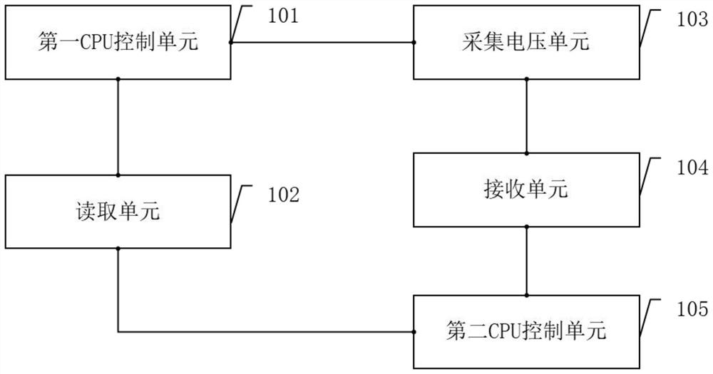
[0021] Such as figure 1 and image 3 As shown, the AC line poor contact fault monitoring device includes: a first CPU control unit 101, a reading unit 102, an acquisition voltage unit 103, a receiving unit 104 and a second CPU control unit 105; the first CPU control unit 101 and the reading unit The unit 102 is coupled; the reading unit 102 is coupled with the collection voltage unit 103; the collection voltage unit 103 is coupled with the receiving unit 104; the reception unit 104 is coupled with the second CPU control unit 105; the collection voltage unit 103 collects voltage data and sends the voltage data to The receiving unit 104, the receiving unit 104 sends the voltage data to the second CPU control unit 105; the second CPU control unit 105 calculates the line resistance according to the voltage, and sends the line resistance to the reading unit 102; the reading unit 102 sends the line resistance To the first CPU control unit 101, the first CPU control unit 101 generat...

Embodiment 2

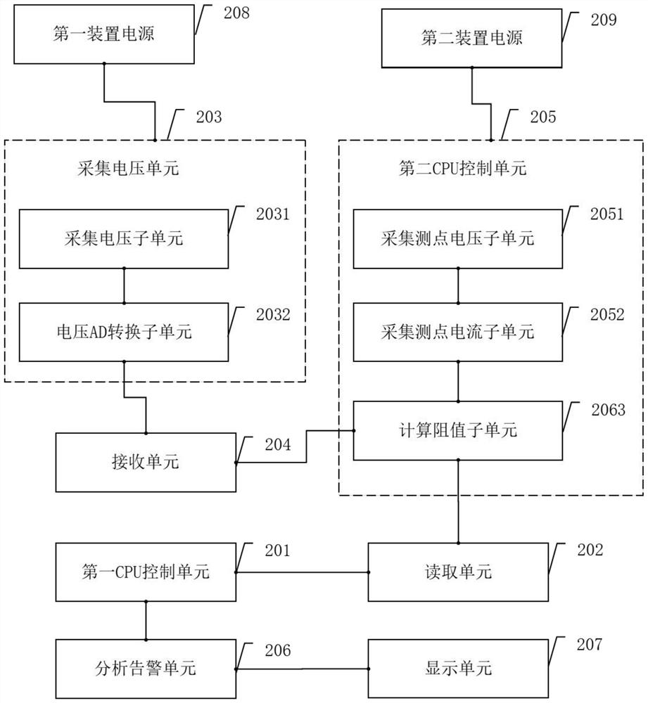
[0028] like figure 2 , image 3 as well as Figure 4 As shown, the AC line fault monitoring device includes: a first CPU control unit 201, a reading unit 202, a voltage collection unit 203, a receiving unit 204, a second CPU control unit 205, an analysis alarm unit 206, a display unit 207, The first device power supply 208, and the second device power supply 209; wherein the second CPU control unit 205 includes: the acquisition measuring point voltage subunit 2051, the acquisition measuring point current subunit 2052 and the calculation resistance value subunit 2053; the acquisition voltage unit 203 includes : the acquisition voltage subunit 2031 and the voltage AD conversion subunit 2031.

[0029] The first CPU control unit 201 is coupled with the reading unit 202; the reading unit 202 is coupled with the acquisition voltage subunit 2031; the acquisition voltage subunit 2031 is coupled with the voltage AD conversion subunit 2032; the voltage AD conversion subunit 2032 is c...


PUM


Abstract

The invention discloses an alternating current line poor contact fault monitoring device which comprises a first CPU control unit, a reading unit, a voltage acquisition unit, a receiving unit and a second CPU control unit, wherein the first CPU control unit is coupled with the reading unit; the reading unit is coupled with the voltage acquisition unit; the voltage acquisition unit is coupled with the receiving unit; the receiving unit is coupled with the second CPU control unit; the voltage acquisition unit acquires voltage data and sends the voltage data to the receiving unit, and the receiving unit sends the voltage data to the second CPU control unit; the second CPU control unit calculates line resistance according to the voltage and sends the line resistance to the reading unit; and the reading unit sends the line resistance to the first CPU control unit, and the first CPU control unit generates a line contact resistance state record according to the line resistance. Maintenance personnel judge whether a load power supply breaks down or not according to the generated line contact resistance state record and repair the fault in time, so that the power production efficiency is improved.

Description

technical field [0001] The invention relates to the technical field of AC power system monitoring, in particular to a fault monitoring device for poor contact of AC lines. Background technique [0002] With the continuous development of society, the use of alternating current is almost everywhere, and most of the alternating current that people use every day is transmitted from substations. However, the power distribution network of the station AC system is tapped and switched by the AC power distribution panel and the distribution box. When the line is tapped, there are busbars, busbars, terminals, various protection devices, etc., and the number of nodes is large. Due to the existence of vibration Or long-term operation leads to rust, which will inevitably increase the resistance of the node contact, resulting in poor contact of the line; while the AC load is mostly a high-power load, when there is a poor contact of the line, the voltage drop will increase, and the voltage...

Claims


Application Information

Patent Timeline
Patent Type & Authority Applications(China)
IPC IPC(8): G01R31/50
Inventor 徐超吴江雄阳国燕龙登其方柳陈斌李河周雄胡贺梅
Owner 广西电网有限责任公司桂林供电局
Why Eureka
Try Eureka