
Tail fiber fixing clamp and fixing method of light emitting sub-module

A technology of optical transmitting sub-module and fixing fixture, which is applied in the field of optical communication, can solve problems such as pigtail breaking, optical power drop, and optical fiber bending, and achieve the effect of avoiding optical power drop

Active Publication Date: 2021-11-19
武汉英飞光创科技有限公司
View PDF8 Cites 0 Cited by
  • Summary
  • Abstract
  • Description
  • Claims
  • Application Information

AI Technical Summary

Problems solved by technology

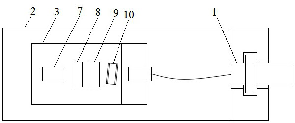
[0005] 1. Adopt the method of allowing the pigtail to straighten naturally. When the temperature drops, the pigtail will shrink under the action of tensile stress, and there is a risk of breaking the pigtail;
[0006] 2. Use the method of letting the pigtail naturally straighten. When the adapter is connected to the external optical fiber, the adapter will shake slightly, and the optical fiber will be subjected to tension, which also has the risk of breaking the pigtail;
[0007] 3. The pigtails are assembled in the form of coiled fibers. Because the space of the coiled fibers is relatively narrow, the optical fibers will be bent more severely, and there is a risk of optical power drop due to excessive bending radius of the optical fibers.

Method used


Image

  • Tail fiber fixing clamp and fixing method of light emitting sub-module
  • Tail fiber fixing clamp and fixing method of light emitting sub-module
  • Tail fiber fixing clamp and fixing method of light emitting sub-module

Examples


Embodiment Construction

[0036] The following will clearly and completely describe the technical solutions in the embodiments of the present invention with reference to the accompanying drawings in the embodiments of the present invention. Obviously, the described embodiments are only some, not all, embodiments of the present invention. Based on the embodiments of the present invention, all other embodiments obtained by persons of ordinary skill in the art without making creative efforts belong to the protection scope of the present invention.

[0037] In describing the present invention, it is to be understood that the terms "center", "upper", "lower", "front", "rear", "left", "right", "vertical", "horizontal", The orientations or positional relationships indicated by "top", "bottom", "inner", "outer", etc. are based on the orientations or positional relationships shown in the drawings, and are only for the convenience of describing the present invention and simplifying the description, rather than in...


PUM

PropertyMeasurementUnit
radiusaaaaaaaaaa
radiusaaaaaaaaaa

Abstract

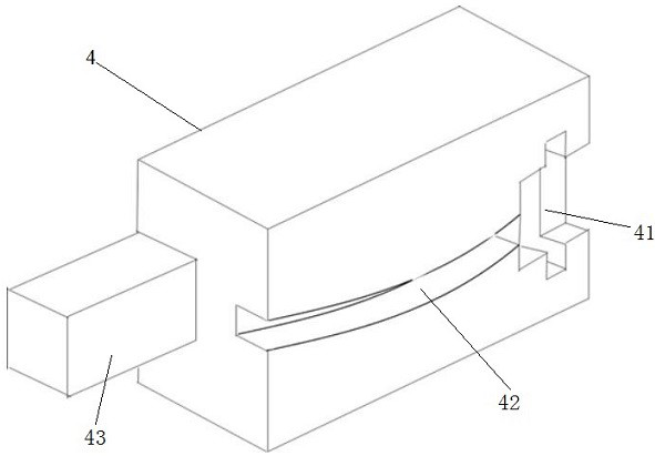
The invention belongs to the technical field of optical communication, and particularly relates to a tail fiber fixing clamp of a light emitting sub-module. The tail fiber fixing clamp comprises a fixing clamp body, wherein a first adapter groove and a tail fiber groove are formed in the top surface of the fixing clamp body, and a crystal head placing table is arranged on the side surface of the fixing clamp body; one end of the tail fiber groove is communicated with the first adapter groove, and the other end extends to the side surface; and the tail fiber groove is bent. The invention further provides a tail fiber fixing method which comprises the following steps of assembling an adapter with a tail fiber on the tail fiber fixing clamp, then, inversely buckling the whole tail fiber fixing clamp on the module shell, so that the crystal head and the adapter are respectively aligned with the crystal head groove and a second adapter groove on the module shell, baking the crystal head and the adapter together to cure glue after pressing, and finally, removing the tail fiber fixing clamp. The tail fiber fixing clamp can automatically adapt to the length of the tail fiber, guarantees that the tail fiber maintains a fixed bending degree after being assembled so as to absorb the tensile force borne by the tail fiber in the using process, can also guarantee that the optical fiber is not excessively bent, and prevents the optical power from falling off due to excessive bending.

Description

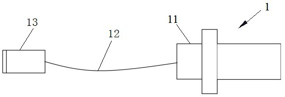
technical field [0001] The invention belongs to the technical field of optical communication, and in particular relates to a pigtail fixing fixture and a fixing method of an optical emission sub-module. Background technique [0002] With the increasing update of 5G communication technology, the demand for high-speed modules such as 25G, 100G, 200G, and 400G in the market is increasing, and the competition in the market is becoming more and more fierce. The cost control and reliability requirements for high-speed modules are also increasing. high. [0003] figure 1 It is a schematic diagram of a typical optical emission sub-module with a pigtail. It includes a module casing, a device cavity opened on the module casing, a laser in the device cavity, a collimating lens, a converging lens, an isolator, and an adapter with a pigtail. like figure 2 As shown, the pigtailed adapter includes the plug on the left, the pigtail, and the adapter on the right. Usually, the method of...

Claims


Application Information

Patent Timeline
Patent Type & Authority Applications(China)
IPC IPC(8): G02B6/42
CPCG02B6/4239G02B6/4256
Inventor 唐永正徐强
Owner 武汉英飞光创科技有限公司
Learn More